Blog

  • アルミニウム合金部品加工技術の開発と展望

    Development and Prospect of Aluminium Alloy Parts Processing Technology

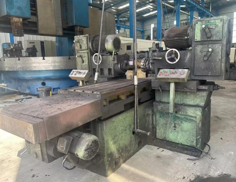
    金属部品加工例写真1:

    CNC 機械加工部品の例 2:

    Development and Prospect of Aluminium Alloy Parts Processing Technology

    アルミニウム合金材料は産業分野で広く使用されています

    工業化のプロセスが深化し続けるにつれて、アルミニウム合金は軽量かつ高強度の重要な材料として、航空宇宙、自動車製造、電子製品などの分野で広く使用されています。アルミニウム合金部品はアルミニウム合金材料の重要な用途であり、その加工技術の開発は業界全体の発展を促す重要な役割を果たしています。

    アルミニウム合金部品加工技術の開発動向

    近年、高度な製造技術の成熟と普及に伴い、アルミニウム合金部品の加工技術も数多くの重要な発展傾向を示しています。まず、CNC 加工装置やインテリジェント製造システムなどのデジタル加工技術が適用され、アルミニウム合金部品の加工精度と効率が向上しました。 2 番目の大きな改善は、先端材料とコーティング技術の統合です。表面コーティングと改質処理により、アルミニウム合金部品の耐食性と耐摩耗性が向上します。さらに、グリーン製造コンセプトの台頭により、低エネルギー消費と低排出の方向に向けたアルミニウム合金部品加工技術の継続的な革新も促進されています。

    大型部品加工開発動向_部品加工起業_部品加工大型開発プロジェクト

    アルミニウム合金部品加工技術の将来展望

    将来に目を向けると、アルミニウム合金部品の加工技術にはまだまだ発展の余地が大きい。新しい材料や新しいプロセスが次々と登場するにつれ、アルミニウム合金部品の加工技術は、パーソナライズされたカスタマイズ要件や小バッチでの効率的な生産のニーズを満たすために、プロセスの最適化とインテリジェントな生産にさらに重点を置くことになるでしょう。同時に、省エネや環境保護の考え方が人々の心に深く根付いており、資源消費と環境汚染を削減するために、持続可能なアルミニウム合金部品の加工技術がますます注目されています。アルミニウム合金部品加工技術は、将来、製造業の変革と高度化の重要な原動力の1つとなり、業界がよりスマートで環境に優しく、より効率的な開発方向に向かうよう促すことが予測されます。

    金属部品加工例写真3:

  • 適切な工業デザイン会社を選択するにはどうすればよいですか? ——お客様必読のご案内

    What is the best way to choose the right industrial design company? --For more information, please click here

    あなたは、数ヶ月、場合によっては数年も頭の中で浮かんできた素晴らしい製品アイデアを持っており、それが市場を変え、ニーズを満たす力があると強く信じています。まったく新しいカテゴリを生み出す可能性さえあると思います。しかし、このアイデアをコンセプトから、成功し、構築可能な素晴らしい製品として店頭 (または Web サイト) に並べるにはどうすればよいでしょうか?適切な工業デザインパートナーを選択することが最も重要なステップです。

    あなたが行う選択は、製品エクスペリエンス、開発コスト、生産サイクル、さらには最終市場の成功または失敗に直接影響します。たくさんのデザイン会社がある中で、どうやって選べばいいのでしょうか?長年この業界に携わってきたデザインチームとして、霧を切り分けて最適なビジネスパートナーを見つけるために、この「お客様必読ガイド」を作成しました。

    ステップ 1: ニーズと目標を明確にする

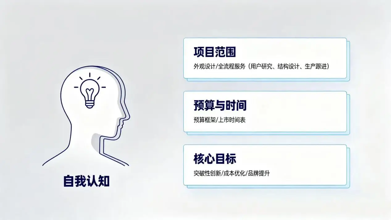
    探し始める前に、まず内側を見てください。明確な自己認識は、パートナーをより効率的に選別するのに役立ちます。

    デザイン会社の能力を見極める_適切な工業デザイン会社を探す_カスタマイズされたリベット溶接プロジェクトのプロセスをお客様と一緒に設計・開発

    単なる外観デザインなのか、それともユーザーリサーチから構造設計、生産フォローまでを一貫して行うサービスなのでしょうか?これはプロジェクトの範囲に関する質問です。

    予算はどのように手配し、時間はどのくらい計画していますか?どのような予算の枠組みを想定していますか?また、市場投入までのスケジュールはどのようなものですか?いわゆる予算について率直にコミュニケーションできることは、実際、設計会社が最も適切な解決策を提供するのに役立ちます。

    中心的な目標は、その設計で解決すると予想される主要な問題は何でしょうか?それは画期的な独自のイノベーションでしょうか、コストの微細な最適化でしょうか、それともブランドレベルでの大幅な改善でしょうか?

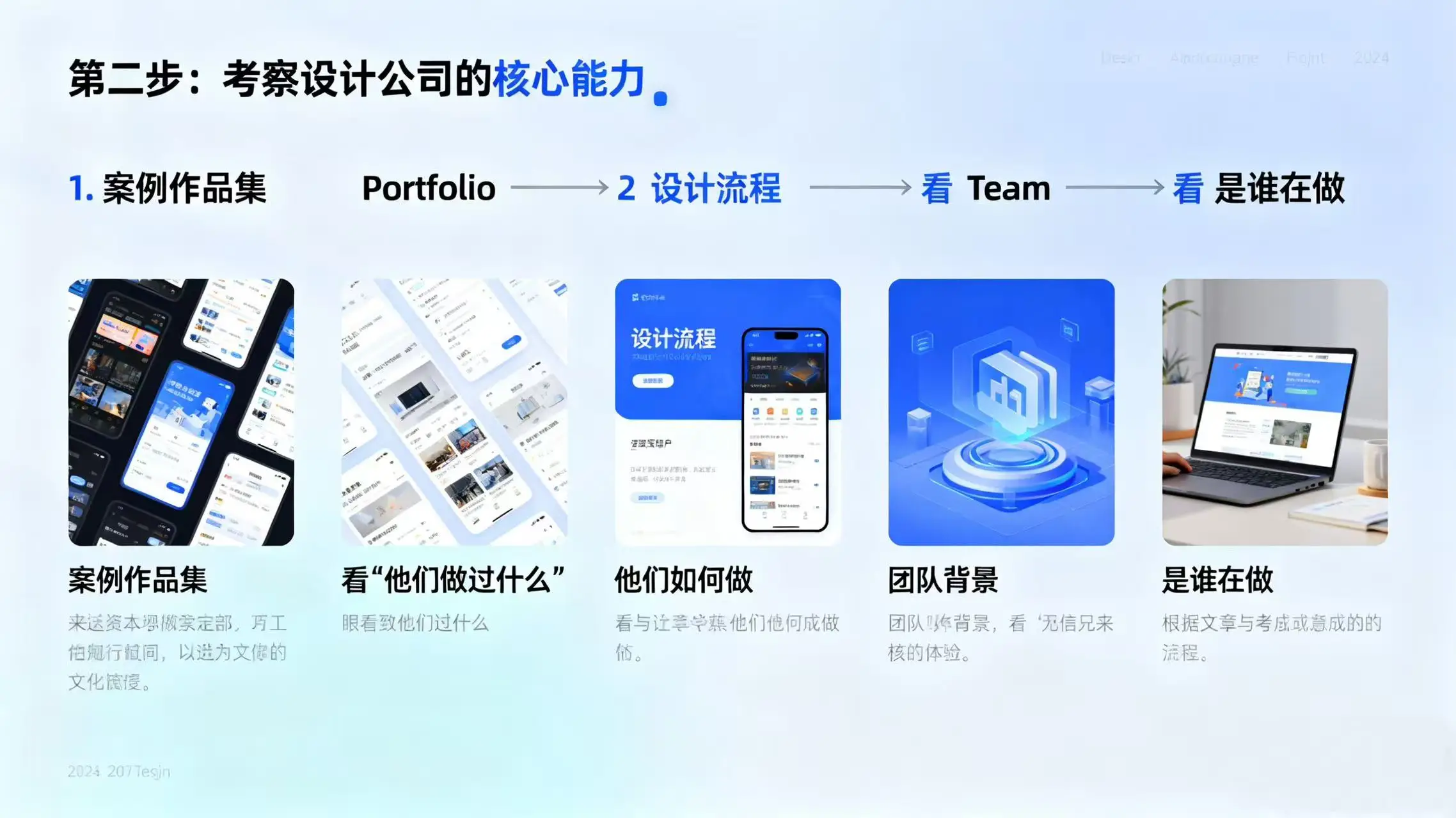
    ステップ 2: デザイン会社の中核となる能力を調査する

    1. ケースポートフォリオ () – 「彼らが何をしたか」を見てください。

    カスタマイズされたリベット溶接プロジェクトのプロセスをお客様と一緒に設計および開発_適切な工業デザイン会社を探しています_デザイン会社の能力を評価

    幅よりも深さに重点を置きます。レンダリングが十分にクールかどうかだけに注目しないでください。彼らの事件の多様性と奥深さを注意深く研究してください。また、家電製品、医療機器、家庭用品など、貴社の製品と同様の分野での経験があるかどうかも考慮してください。

    プロセスと結果はどちらも同様に重要であると見なされるべきです。優秀な企業は自社の設計プロセスを積極的に公開してくれるでしょう。この設計プロセスには、ユーザー調査、スケッチ、モデルだけでなく、エンジニアリングの詳細も含まれます。これは彼らの思考の深さと問題解決能力を証明するものであり、彼らは単なるいわゆる「アーティスト」ではありません。

    完成した作品は、最終的に量産可能な実際の製品にどれだけのデザインを進化させたかに注目しており、デザインとエンジニアリングおよび生産を組み合わせる能力を直接証明しています。

    2. 設計プロセス () – 「どのように行うか」を参照してください。

    標準的な設計プロセスについて質問して、それが体系的であるかどうかを確認してください。成熟した設計会社は、プロジェクトを秩序正しく進めてリスクを軽減できるように、需要分析から始まり生産サポート段階に至る完全かつ体系的な方法論を持っている必要があります。

    研究に焦点を当てているかどうかが焦点となる。デザインは決して根拠のない想像に基づくものではありません。プロジェクトの初期段階でユーザー調査を行っているか、市場分析を行っているか、競合製品の調査を行っているかなどを調べる必要があります。これにより、設計の方向性が正しいかどうかが決まります。

    エンジニアリングおよび生産サポートを含めることはできますか?これは最も重要な差別化ポイントの 1 つです。構造設計 (ME)、その後の金型フォローアップ、および生産調整 (製造可能性分析サービスのための設計) である DFM を提供するか、提供するために協力することを保証する必要があります。制作できないデザインは高価なスケッチです。

    3. チームの背景 (チーム) – 「誰がそれをやっているのか」を確認する

    チームの構成は何ですか? チームは経験豊富な上級デザイナーによって率いられていますか?チームメンバーはデザイン、エンジニアリング、材料などの多様なバックグラウンドを持っていますか?

    接続チャネル: あなたの重要な接続パートナーは誰になりますか?この人はあなたが本当に望んでいることを理解し、それをスムーズに伝えることができますか?

    ステップ 3: 協力の適合性を評価する

    1. コミュニケーションと化学反応 ()

    適切な工業デザイン会社を探す_デザイン会社の能力を評価する_お客様と一緒に設計・開発するカスタマイズされたリベット溶接プロジェクトのプロセス

    最初のコミュニケーションでは、相手があなたのニーズを本当に聞いているのか、それとも自社のソリューションを売り込むことに熱心なのかを理解するように努めてください。良好なコミュニケーションはプロジェクト成功の基礎です。

    彼らとコミュニケーションを取る気はありますか?この種のコミュニケーションは、スムーズなコミュニケーションと同じ頻度の思考が特徴であり、プロジェクトの協力サイクルは数か月に及ぶ場合もあるため、このようなチームと協力することが非常に重要です。

    2. 知的財産 (IP) は明確かつ透明です

    協力を開始する前に、知的財産権の所有者を明確にすることが重要です。これらの正式な会社は、設計結果の所有権がクライアントに属することを明確に示す標準契約書を提供します。契約条件があいまいな会社に遭遇した場合には、十分な警戒を続ける必要があります。

    3. 引用方法()

    デザイン会社の能力を評価_顧客と協力して設計・開発したカスタマイズされたリベット留めおよび溶接プロジェクトのプロセス_適切な工業デザイン会社を探しています

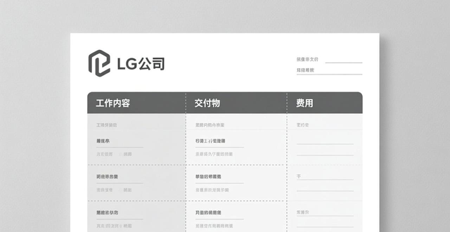
    見積もりが固定のプロジェクト ベースに基づいているのか、それともコストが時間に基づいて計算されているのかを確認します。ご依頼・お見積りはできる限り詳細に行い、作業内容、成果物、各段階の費用を明確に記載し、後々意見の相違が生じることのないようにお願いいたします。

    警戒すべき「赤信号」

    ビジネスを関与させるのではなく、アートについてだけ話してください。デザインはビジネスの目標を達成する必要があります。相手が作品の「芸術性」だけを強調し、その市場価値やユーザー価値を明確に説明できない場合には、慎重に扱う必要があります。

    「問題ありません」「満足は保証されます」という約束には懐疑的になってください。これは過剰約束に該当します。プロフェッショナルなデザインは継続的な探求のプロセスであり、プロフェッショナルなデザインは継続的なテストのプロセスでもあり、プロフェッショナルなデザインは継続的な最適化のプロセスでもあり、プロフェッショナルなデザインは客観的な法則を尊重する必要があります。

    「見た目だけ責任を持って、あとは自分でやってください」と主張する企業は、エンジニアリングや生産を無視しているため、デザインを実装する際に多くの困難に直面する可能性が高く、コストが大幅に増加します。

    明確なワークフローやプロジェクト管理方法を持たない企業は、プロジェクトの実行中に混乱が生じる危険があります。

    自分の総合的な判断を信頼してください

    この選択は非常に重要な戦略的決定です。単にサービスを購入するだけではなく、パートナー間の関係を始めることがより重要です。

    最終的な意思決定は、合理的な評価(事例、プロセス、能力など)と感情的な判断(コミュニケーションの状況、相互信頼、適合度など)の組み合わせで行われるべきです。最終候補企業 2 ~ 3 社と綿密なディスカッションを行い、企業の強みを総合的に評価するために小さなテスト問題を与えることをお勧めします。

    このガイドがあなたの今後の道を照らしてくれることを願っています。優れた設計パートナーは、製品の成功を促進します。彼らは専門的な知識と経験を持ってお客様のビジョンを守り、見た目が美しく、商業的に価値があり、ユーザーに愛される素晴らしい製品を作成するために協力します。

    ようこそ、Artisan Design と協力して製品の将来の方向性を探求してください。私たちは、プロフェッショナルなプロセスと成功体験によって、あなたの創造性を強化したいと考えています。

  • 半導体装置部品分野の概況

    Overview of Semiconductor Device Part Segments

    今日は半導体装置部品セクターについて簡単に振り返ってみたいと思います。

    半導体産業は幅広い産業をカバーしています。以前は、半導体の設計と製造の側面が市場からより注目を集めていました。世界的な経済不況による需要の減少と、最近の半導体の在庫削減サイクルを考慮すると、これらのリンクの繁栄はついに衰退しました。

    しかし、半導体装置セクターでは、国内代替のプロセスから恩恵を受けている企業もある。機器部品セクターでは、この恩恵を受けた企業もある。消耗品などの分野では、国内代替のプロセスから恩恵を受けた企業もある。業界全体からの影響は比較的少ないです。主にこれらのリンクを整理しています。

    1. 設備

    チップの作製工程は以下の通りです。

    北華荘社などの熱処理装置、北華荘社や拓京科技社の成膜装置、上海マイクロエレクトロニクス社製のフォトリソグラフィー装置、チャイナマイクロエレクトロニクス社や北華荘社のエッチング装置、華海青科社製の研磨装置、上海盛美社の洗浄装置など、さまざまな設備が使用される。最後に試験装置ですが、株式会社サイテングが取り扱っております。

    最近、米国は国内の先端プロセス半導体に対する新たな規制を開始した。市場は、一部の機器会社が主要リンクでボトルネックに遭遇するのではないかと懸念している。さらに、設備企業のこれまでのバリュエーションはすでに高水準にあるため、短期的には設備企業の確実性は若干低くなります。

    2. 消耗品

    材料に関与している企業はさらに多数あり、複雑なので、ここでは簡単にリストします。

    ケメットガス、ウォルターガス、ナンダオプトエレクトロニクスなどの特殊ガス。

    フォトレジスト、湿式電子化学薬品(上海信陽、京瑞有限公司など)

    Anji Technology、Dinglong Co., Ltd.などの研磨材。

    ターゲットとしては、リーダーは江豊電子だ。

    半導体の景気が低迷すると、消耗品の使用にもある程度の影響が出ます。しかし、国内代替の加速から恩恵を受ける構造的な機会がいくつかあるはずだ。ここではそれらを一つ一つ分析するつもりはありません。能力を持つ友人はさらに詳細な研究を行うことができます。

    3. 部品

    これは現在最も論理的なリンクであり、私が注目しているリンクでもあります。

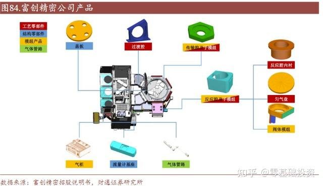
    エッチング装置を例に挙げます。この装置は、マニピュレーター、コールドポンプ、静電チャック、真空計など、さまざまなシステムやコンポーネントで構成されています。具体的な状況を下の図に示します。

    具体的にはこの3社を中心に見ていきました。

    1. 富荘精密は主に半導体精密金属部品の加工・製造を行っております。製品カテゴリーは非常に豊富で、年間平均3,000種類の部品を顧客に納入しており、7nmプロセス部品の生産能力も備えている。確実性が高く、成長も早い。唯一の欠点は評価が若干高いことです。現時点で来年のバリュエーションはまだ70倍を超える。

    真空半導体の超高清浄度_真空チャンバーや半導体装置の高気密高精度リベッティング_半導体真空技術

    2. シンライ・インカイ

    同社は高純度ステンレス鋼を母材とし、清浄度が高く純度の高い状態を呈する応用材料を主力事業としている。主な製品には、ポンプ、バルブ、フランジ、プラスパイプ、管継手などがあります。

    真空半導体の超高清浄度_半導体真空技術_真空チャンバーや半導体装置の高気密精密リベッティング|真空半導体の超高清浄度_真空チャンバーや半導体装置の高気密精密リベッティング_半導体真空技術|真空チャンバーや半導体装置の高気密精密リベッティング_真空半導体の超高清浄度_半導体真空技術

    高清浄流体パイプライン システムは、超高真空システムの重要なコンポーネントです。同社の製品は半導体分野に関連するほか、食品安全や生物医学の分野でも使用されています。参入の敷居は比較的高いです。国際的には、ヨーロッパ、米国、日本、韓国の製品が大半を占めていますが、中国での市場シェアは 5% 未満であり、一部の製品はすでに国際市場に参入しています。

    3.正帆テクノロジー

    同社は中国の大手プロセスメディア供給システムプロバイダーであり、電子プロセス機器、バイオ医薬品機器、電子ガス、MROサービスに特化し、半導体部品用ガスキャビネット関連の事業を拡大しています。ガスキャビネットシステムは、エッチング装置、蒸着装置、イオン注入装置に必要です。

    興味深いのはガスホルダー事業です。国内市場は輸入に大きく依存しています。 Zhengfanは機器部品の分野に参入したばかりです。ガスホルダー事業は、以前の事業と技術的に類似点があります。

    欠点は、Zhengfan のビジネスが非常に複雑であるため、分割して個別に評価する必要があることです。その結果、評価はさらに難しくなるでしょう。

    市場ニュース:

    1. バークシャーはTSMCを買収した。かつてバフェット氏の最初のTSMC買収は、半導体セクター全体の上昇をある程度牽引した​​。現在、半導体セクターの最近の在庫削減サイクルは底打ちの兆しを見せています。しかしブームは一転。すでにその時点に達しているかどうかについてはさらなる観察が必要だが、一つ確かなことは、現在の景気後退と需要低迷により、たとえ半導体に新たな上昇サイクルが到来したとしても、その勢いはそれほど大きくないということだ。

    バフェット氏の運用については、私もそう感じており、過度に解釈する必要はありません。結局のところ、成熟した投資家にとって、長期にわたって安定して高い収益を得ることができるかどうかは、特定の運用に依存するのではなく、投資システム全体に依存します。一つの手術を見てみると、正しいか間違っているかは実際には普通のことです。

    2. Tencent は第 3 四半期報告書を発表しました。総収益は前年比2%減の約1,400億元で、前月比5%増加した。純利益は約320億元で、前年同期比2%増、前月比15%増でした。アリババも第3四半期報告書を発表した。

    この四半期、アリババの収益は 2,071 億 7,600 万元に達し、前四半期比 0.4% 増加しました。純利益は338億2,000万ドルで、同時期と比較して18.6%増加した。

    収益はもはや増加傾向を示していませんが、利益は増加しています。これは、これらのインターネット大手企業がコスト削減と効率向上において優れた成果を上げていることを示しています。しかし、コストを削減するだけでは企業は大きくなりません。このような状況では、企業に他に成長ポイントがない限り、株価収益率ではなく、配当率に注目することをお勧めします。

    まずテーブルが調整され、半導体部品分野の3社がテーブルに追加され、Peneng Technologyが家計の貯蓄から取り除かれた。その主な理由は、来年生産されるバッテリーセルの数が増えるためです。それに比べて、インバーターパターンはわずかに優れています。

    パブリックアカウント: ゼロベースの投資。論理、意見、堅実なオファーに注目してください。

    ———————————————————

    真空半導体の超高清浄度_真空チャンバーや半導体装置の高気密高精度リベッティング_半導体真空技術

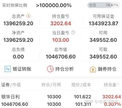
    実際のオファー(参考のみであり、投資アドバイスを構成するものではありません)

    2018年末から2021年末までの利益は440,000、年複利は35%です。

    今日はオペレーションなし、損益なし、ポジション0%、22年で35万の利益。

    真空半導体の超高清浄度_半導体真空技術_真空チャンバーや半導体装置の高気密精密リベッティング|真空半導体の超高清浄度_真空チャンバーや半導体装置の高気密精密リベッティング_半導体真空技術|真空チャンバーや半導体装置の高気密精密リベッティング_真空半導体の超高清浄度_半導体真空技術

  • 微小・複雑な薄肉部品を加工するための精密治具とそ​​の制御方法

    Precision jigs and their control methods for processing small and complex thin parts

    技術的な紹介:

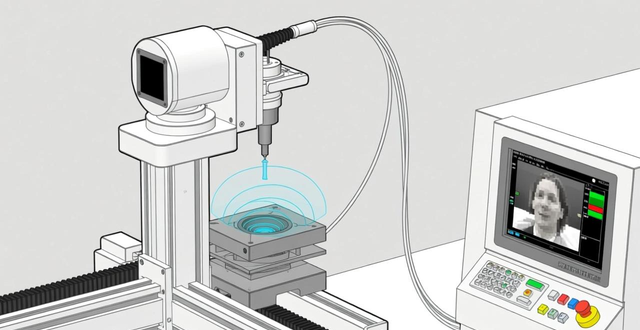
    マイクロサイズの複雑な薄肉部品の加工における位置決め精度の低さと従来の治具の適応性の低さの問題を考慮して、本発明は、気液減衰シリンダと多軸制御システムを統合した精密治具を提案する。 5組のユニバーサルジョイントで接続された気液減衰シリンダーは、リフト量0~80mm、たわみ量0~270°を実現します。気液減衰シリンダは、視覚システムからのリアルタイムフィードバックと産業用コンピュータの集中制御を組み合わせて、クランプ力と姿勢を正確に調整します。これにより、複合工作機械では一度のクランプで多工程の加工が完了し、加工効率と精度が大幅に向上します。

    キーワード: 精密治具、気液減衰シリンダ、視覚制御

    Precision jigs and their control methods for processing small and complex thin parts

    【技術分野】

    本発明は、微細工作機械加工に用いられる精密治具及びその制御方法に関する。特に、微小で複雑な薄肉部品の加工に使用される精密治具とそ​​の制御方法に関する。一般に、メソ/マイクロのクロススケール処理技術の分野に分類されます。はい、まさにその通りです。

    【背景技術】

    極小部品を加工する場合、工作機械を切り替える際に頻繁に部品を掴む必要があります。全体の構造サイズが小さく、体積も小さいため、紛失したり破損したりしやすいです。機能面が小さく、位置変更やクランプの信頼性が低く、変形しやすいです。加工精度が損なわれ、ひどい場合は部品を廃棄することになります。

    特に、複雑な構造、小さなラインサイズ、多数の加工手順、および非常に高い精度要件を備えた精密微細構造部品の場合は、従来の分散プロセス方法を使用する必要があります。複数の工作機械では複数回のクランプや位置決めを経て加工が行われるため、加工品質を保証できないことがよくあります。また、一部の部品では加工合格率や加工効率が特に低くなります。

    まずはクランプ回数を減らし、それによる複数の位置決め誤差の蓄積を回避し、加工精度を向上させる必要があります。この方法によってのみ、プロセスの高い信頼性を効果的に確保し、欠陥のない生産を達成することができます。

    さらに、複数のクランプに必要な位置決め時間を節約し、加工時間と各プロセス間の補助時間を短縮し、使用する工作機械の数を減らし、材料の流れを簡素化することで、部品の加工と成形に費やす時間を大幅に短縮し、生産効率を向上させ、生産設備の柔軟性をさらに向上させ、工作機械設備全体が占有する床面積を削減し、投資コストを節約することができます。

    【発明の内容】

    本発明の目的の一つは、複合工作機械におけるワーク全体の加工を一度のクランプで完了することができ、微細で複雑な薄肉部品の加工に適した、簡単な構造と合理的なレイアウトを備えた精密治具を提供することにある。

    上記の目的を達成するために、本発明によって解決される技術的課題は、厚さ0.1〜0.5mmの薄肉加工材料の効果的な吸引、位置決め、およびクランプをどのように達成するかである。昇降0~80mm、たわみ0~270°が可能で、任意の空間でホバリングして姿勢を保持できる精密治具の昇降・たわみプラットフォームをどのように実現するか。

    技術的解決策は、上記の技術的問題を解決するために、本発明がマイクロサイズの複雑な薄肉部品を加工するための精密治具を有することである。この固定具には、ベース、昇降可能な偏向プラットフォーム、および 5 つの気液減衰シリンダーが含まれています。ベースは一体構造で、下部が厚く上部が薄い2つのセクションに分かれています。全体の形状は平坦な段付きシャフトです。

    昇降可能な偏向プラットフォームは円形のプレートです。

    ベースと昇降可能な偏向台は上下に平行に配置され、全体として上記5本の気液減衰シリンダーを介して接続されている。

    前述したように、5 つの気液減衰シリンダーのうち 1 つは中央の気液減衰シリンダーです。中央気液減衰シリンダの中心軸とベースおよび昇降可能な偏向プラットフォームの中心との間の接続線は同一直線上にある。

    上記の5つの気液減衰シリンダは、次の方法でベースおよび昇降可能な偏向プラットフォームに接続されている。すなわち、中央の気液減衰シリンダの下端が自在継手によってベースに回転可能に接続され、中央の気液減衰シリンダの上端がボールピンを介して昇降可能な偏向プラットフォームに回転可能に接続されている。

    このうち、他の4つの気液減衰シリンダは全て周辺気液減衰シリンダである。各周囲の気液減衰シリンダーの上端は、昇降可能な偏向プラットフォームとの回転可能な接続を形成します。接続箇所4ヶ所は全て上部ユニバーサルジョイントです。これらの4つの上部ユニバーサルジョイントは、昇降可能な偏向プラットフォームの下面の縁の内側の同じ円周面上に均等に配置されている。

    各周囲の気液減衰シリンダの下端は、ベースに対して回転可能な連結状態を形成している。 4 つの回転可能な接続はすべて下部のユニバーサル ジョイントです。これら4つの下部ユニバーサルジョイントは、ベースの上面の縁部の内側の同一周面上に均等に配置されている。

    真空吸引カップが昇降可能な偏向プラットフォームの上面の中央に設けられています。

    半径方向に沿って、真空吸引カップの外壁と昇降可能な偏向プラットフォームの端の間にある昇降可能な偏向プラットフォームの上面に 4 つのスライド レールが均等に配置されています。

    上記4本のスライドレールのうち、各スライドレールの内側にはスライドブロックが設置されている。各スライドブロックの上面には、垂直方向に延びる直立した連結軸が設けられており、各スライドブロックの上面には連結軸が設けられている。各連結軸の上端面には、当該連結軸に直交し、クランプの中心軸方向に向けて押さえ板が固設されている。

    押圧板と連結軸は一体構造となっており、各押圧板の端部下面には直角の切り欠きが設けられている。この直角の切り欠きは、真空吸盤の上部に置かれ、加工を待つ小さな複雑な薄肉部品の端を差し込み、クランプして固定するために使用されます。その深さと長さの寸法は、処理を待っている小さく複雑な薄肉部品の厚さとサイズに一致します。

    上記の各スライドレールには、真空吸着カップの隣に電磁石が設置されています。各電磁石のコイルは外部電源に接続され、電磁力を発生させてその上の対応する圧迫板を下方に吸引します。

    上記の微細で複雑な薄肉加工部品と真空吸盤の上面との間には、両面粘着フィルムの層が貼られています。

    微小で複雑な薄肉部品を加工するための上記の精密治具の特徴は、一定数の長尺ガスケットも内蔵していることです。

    スライドブロックとスライドレールの隙間には、必要に応じてガスケットが挿入されます。

    さらなる改良として、スライド レールの両側に細長い貫通穴が設けられています。スライドレールの幅方向に沿って、スライドブロックと電磁石との間にも位置決め用のボルトが設けられている。

    さらに好ましくは、上記基体上において、下側部分と上側部分との接続によって形成される段差部には、縁から放射状に多数の帯状の透明な位置決め穴が均等に開口されている。短冊状の透明な位置決め穴の目的は、精密治具全体を微細加工プラットフォームのベース上に組み立てる際の位置決めを行うことです。

    さらに好ましい選択肢では、微小で複雑な薄肉部品の加工に使用される上記精密治具において、精密治具全体が微細加工プラットフォームのベース上に組み立てられるとき、ベースと微細加工プラットフォームのベースとの間にゴム製の衝撃吸収パッドも設けられる。

    さらに好ましくは、上記真空吸引カップは、自動数値制御真空吸引カップである。

    さらに、さらに最適化するために、微小で複雑な薄肉部品の加工に使用される上記の精密治具には、実際に、外部真空システム、油圧システム、電磁微小力圧縮システム、および次のような視覚イメージング システムが含まれます。

    真空システムの最後に 3 番目のエアフィルターが設けられる場合があります。第3エアフィルタは配管を介して真空吸盤に接続されており、第3エアフィルタと真空吸盤との間にも圧力計が設けられている。

    このような油圧システムは、5つの気液減衰シリンダにそれぞれ接続されている。その目的は、各気液減衰シリンダーを駆動して動作を実行することであり、動作の実行は油圧システムによって実現されます。

    本説明における電磁システムは、4つの電磁石にそれぞれ接続されており、各電磁石のコイル電流を制御することを目的としている。

    微細部品加工ツール_小物部品の加工方法_小物部品の加工・クランプソリューション

    いわゆる視覚イメージングシステムは、精密治具の側面上の設置位置に配置されます。精密治具全体の動作状態を同期して撮像し、取得した画像データや情報を外部の産業用コンピュータに送信します。その後、産業用コンピュータ内にリアルタイム画像処理用に特別に用意されたソフトウェアによって画像処理プロセスが実行されます。

    私たちが話している真空システムには、並列接続された 2 つの制御ループが含まれています。そのうちの 1 つは第 1 ループと呼ばれ、もう 1 つは第 2 ループと呼ばれます。

    第一ループの端はエアフィルターに接続されており、真空ポンプを使用して真空吸盤を真空にし、吸着力を発生させます。

    第2の回路の一端はエアフィルタに接続されており、その機能は真空吸盤内に圧縮空気を送り込み、真空吸盤内の真空状態を破って通常の大気圧状態に戻し、真空吸盤の吸着力をゼロにすることである。

    最初の回路の終わりから始まりまでの接続順序は次のとおりです。最初に真空スイッチ、次に最初の 2 位置 2 方ソレノイド バルブです。ここで、第 1 の 2 位置 2 方向ソレノイド バルブの一方のポートは第 1 の空気容積に接続され、もう一方のポートは第 1 の真空制御キットの空気入口に接続されます。前記第1の真空制御補機は、順に接続された第1のエアフィルタ、第1の減圧弁および第1の空気圧計から構成される。上述の第1の真空制御アクセサリの空気出口は、真空ポンプおよび第1の真空発生器に順に接続される。 。

    それぞれは、終端から始端への接続順序を持ち、第 1 タイプのコンポーネント、つまり一方向スロットルバルブ、第 2 タイプのコンポーネント、つまり第 2 の 2 位置二方ソレノイドバルブ、第 3 タイプのコンポーネント、つまり第 2 の真空制御コンポーネント、および第 4 タイプのコンポーネント、つまり第 2 回路の圧縮空気源となります。

    第2の2位置二方ソレノイドバルブに接続された第2の真空制御アセンブリの空気出口端は、圧縮空気源の空気入口端に接続されている。上記第2真空制御アセンブリは、順に接続された第2空気圧計、第2減圧弁、第2エアフィルタおよび第3エアフィルタから構成される。

    (2) 油圧システムには、油圧制御コンポーネントと空圧制御コンポーネントが含まれます。

    オイルカップ、ワンウェイバルブ、スロットルバルブは一緒になって油圧制御コンポーネントを構成します。スロットルバルブは、気液減衰シリンダ内の油圧シリンダのオイル出口ポートに接続される。一方向弁の出口端は、気液減衰シリンダの油圧シリンダの油入口に接続され、油圧シリンダと気液減衰シリンダのスロットルバルブは作動油配管を介して接続されており、作動油の閉回路循環を形成している。

    鉛直方向において、上記オイルカップの高さは、気液減衰シリンダの頂部の高さよりも高く、

    いわゆる空気圧制御コンポーネントは、第 2 の圧縮空気源と 2 位置の N 方向電磁逆転バルブをカバーします。このうち、2位置N方電磁切換弁のエア出口ポートは、気液減衰シリンダのシリンダのエア入口に接続されている。 2位置N方電磁切換弁の空気入口ポートは、気液減衰シリンダシリンダの空気出口に接続され、圧縮空気閉回路サイクルを形成する。

    (3) 電磁微小力圧縮システムは、圧縮プレートの下面に取り付けられた極薄の圧電センサーを備えています。超薄型圧電センサーは、加工対象の微小で複雑な薄肉部品にかかる電磁力の大きさを検出するために使用されます。

    対物レンズ、画像伝送ビーム、伝送ビーム、画像取得カード、および画像処理ソフトウェアは一緒に視覚イメージング システムを構築し、マイクロサイズで複雑な薄肉部品の加工に使用される精密治具の上部に配置されます。

    上記の技術的解決策は、このような技術的効果を直接もたらす。精密治具全体はシンプルな構造、コンパクトで合理的なレイアウトを備えており、厚さ0.1〜0.5 mmの薄肉加工材料の効果的な吸着、位置決め、クランプの要件を十分に満たすことができます。精密治具の昇降・偏向プラットフォームとして、0~80mmの昇降、0~270度の偏向を実現し、任意の空間内で必要な姿勢を維持するホバリングが可能です。複合工作機械のワーク加工全体を1回のクランプで完了できる精密治具の技術要件を十分に満たしています。微小・複雑な薄肉部品の加工に適しています。

    上記の技術的効果をよりよく理解するために、簡単な分析と説明は次のとおりです。

    上記の技術的方法では、両面テープの使用、小型の自動数値制御真空吸引カップの使用、つまり CNC 真空吸引カップの使用、および一連の真空システム技術手段の使用は、処理対象の薄肉部品の信頼性の高い吸引と位置決めを確保するのに非常に効果的です。クランププレートと電磁石の協働により、加工対象の薄肉部品の真上にある表面が確実に圧縮効果を達成し、側面が絞り位置を達成することができます。

    2.上記の技術的解決策では、周囲に4つの気液減衰シリンダがあり、その上端と下端がそれぞれユニバーサルジョイントによって接続されている。中央の気液減衰シリンダーもあり、その下端はユニバーサルジョイントを介してベースに回転可能に接続され、上端はボールピンを介して昇降可能な偏向プラットフォームに回転可能に接続されています。これらにより、昇降可能な偏向プラットフォームは、薄肉部品の加工要件に応じて、0 ~ 80 mm で昇降、0 ~ 270° で偏向でき、必要に応じてあらゆる空間でホバリングできます。

    現在のページ 1 1 2 3 4

  • Five Key Considerations and Brand Comparison When Purchasing CNC Machine Tools

    Selection of Machine Tools — A Foundational Investment for Enterprise Production Capacity
    The average lifespan of a numerically controlled machine tool reaches 15 to 20 years, and the decision to purchase one often impacts a company's manufacturing capacity for the next decade. The global CNC machine tool market is projected to reach US$100 billion by 2024. Faced with hundreds of brands and thousands of models, how should procurement officers make prudent decisions amidst such complexity? Industry research indicates that 65.11% of enterprises experience decision-making errors of varying degrees in machine tool procurement, resulting in an average loss of 23.11% in expected value. This paper adopts a practical perspective to analyse five core selection criteria in detail and provides objective comparisons of major brands, thereby assisting enterprises in establishing a scientific machine tool procurement decision-making framework.

    Part One: Precision Performance Metrics — Practical Considerations Beyond Nominal Data
    1.1 Positioning Accuracy and Repeatability
    Interpretation of International Standards

    ISO 230-2 Specification: International Standard for Acceptance Inspection of Machine Tools

    Test method: Full-length measurement using a laser interferometer, with corrected data at one-metre intervals

    Industry benchmark values:

    Conventional machine tools: Positioning accuracy ±0.01 mm, repeat positioning accuracy ±0.005 mm

    Precision machine tools: Positioning accuracy ±0.003 mm, repeat positioning accuracy ±0.0015 mm

    Ultra-precision machine tools: Positioning accuracy within ±0.001mm

    Practical considerations
    Temperature effect: While nominal accuracy is typically obtained at a constant temperature of 20°C, variations arising from temperature differences of ±2°C (approximately 0.002 mm/m) must be considered in actual working environments.

    Consistency throughout the entire travel: Focusing on the precision deviation at both ends of the travel, high-quality machine tools should maintain a deviation of no more than 150% relative to the nominal value.

    Long-term stability: Accuracy decay within six months should be less than 201 TP3T.

    Test proposal:

    Require suppliers to provide third-party inspection reports

    Field machining tests on ISO specification test pieces (e.g., NAS 979 test pieces)

    Testing of Accuracy Retention under Different Load Conditions

    1.2 Geometric Accuracy and Dynamic Accuracy
    Principal geometric error terms:

    True straightness: ≤0.008 mm/m within the XY plane (Precision grade)

    Verticality: Verticality between shafts ≤ 0.008 mm/500 mm

    Radial runout of the spindle: ≤0.003 mm (near end), ≤0.006 mm (at 300 mm)

    Dynamic precision performance:

    True roundness test: True roundness of ∅100mm in machined condition ≤0.01mm

    Contour accuracy: Actual contour error in complex surface machining

    High-speed precision: Accuracy degradation when tested at 80% of maximum speed

    Case Comparison:
    An automotive mould manufacturer tested three brands of machine tools of the same specification:

    Brand A (Germany): Dynamic roundness 0.008mm, price 2.8 million yuan

    Brand B (Japan): Dynamic roundness 0.012mm, price ¥1.9 million

    Brand C (Taiwan): Dynamic roundness 0.018mm, price 1.2 million yuan
    Final decision: Purchase one unit of Brand A for precision machining and three units of Brand C for rough machining, thereby achieving a balance between precision and cost.

    Part Two: Rigidity, Power and Thermal Stability
    2.1 Structural Rigidity Analysis
    Bed Frame Structural Design:

    Material selection:

    Cast iron: A traditional choice, offering excellent damping properties (HT300 and above)

    Polymer concrete: An emerging material with a vibration damping ratio 6 to 10 times higher than cast iron.

    Steel plate welding: Lightweight design, suitable for high-speed machine tools

    Structural Optimisation: Through finite element analysis-based optimisation of rib placement, the top brand achieves a stiffness-to-weight ratio 30-50% higher than that of general brands.

    Spindle system rigidity:

    Spindle tip displacement: Deformation under rated cutting force

    Typical values: Hard-rail machine tools ≤0.015mm, Linear guide high-speed machine tools ≤0.025mm

    Test method: Apply radial force and measure displacement using a micrometer.

    Guide rail and ball screw configuration:

    Hard rails vs linear rails: Hard rails possess 3 to 5 times the load-bearing capacity, whilst linear rails achieve 2 to 3 times the speed.

    Lead screw diameter: ∅40mm and above are heavy-duty cutting specifications.

    Preload adjustment: Clearance elimination via double-nut preload

    2.2 Detailed Evaluation of Spindle Performance
    Output and Torque Curve:

    Fixed power range: A wide range (e.g., 1:8) is preferable to a narrow range.

    Maximum torque: Focus on torque in the low-rev range, for example the torque value at 200 rpm.

    Overload capacity: Short-term overload capacity (e.g. 150%, 30 minutes)

    Selection of Spindle Type:

    Gear-driven spindle: Capable of high torque and heavy-duty cutting, though maximum rotational speed is restricted (typically ≤6000 rpm).

    Direct-drive electric spindle: High rotational speed (12,000–40,000 rpm), high precision, but torque is comparatively low.

    Hybrid spindle: Achieves both high-speed rotation and high torque through a two-stage design.

    Cooling and Thermal Management:

    Spindle oil cooling: Temperature control accuracy ±1°C

    Automatic adjustment of bearing preload: Reducing the effects of thermal expansion

    Thermal Symmetry Design: Reducing Spindle Tilt

    Actual performance data comparison:

    Brand/Model Output (kW) Maximum Torque (Nm) RPM Range Rated Power Range Price Range
    Muye S500 22/26 140 50-12000 1:10 1.8-2.2 million
    DMG DMU50 27/34 170 30-12000 1:8 1.6-1.9 million
    HAS VF4 22/26 122 50-7500 1:5 800,000-950,000
    2.3 Thermal Stability Engineering
    Temperature Control Strategy:

    Constant temperature of key components: forced cooling of the spindle, lead screw, and bearings

    Thermosymmetric design: Reducing non-uniform thermal deformation

    Environmental Adaptation: Equipped with a temperature sensor for automatic compensation

    Thermal drift index:

    Accuracy variation during 4-hour continuous operation: Precision machine tools ≤ 0.008 mm

    Poor precision of cooling and heating units: High-quality machine tools ≤0.005mm

    Ambient temperature compensation: Automatic compensation within the range of 5 to 35°C

    Part Three: Control Systems and Intelligent Functions
    3.1 Comparison of Mainstream Control Systems
    Three major system camps:

    Siemens SINUMERIK (Germany):

    Market share: Approximately 35% in the global high-end market

    Strengths: 5-axis machining, lathe and milling combined machining, digital integration

    Representative models: 840D sl (high-end), 828D (mid-range)

    Intelligent functions: adaptive control, process cycle management, digital twin compatibility

    FANUC (Japan):

    Market share: Approximately 45% in the global mid-to-high-end market

    Strengths: High stability, excellent usability, comprehensive ecosystem

    Representative models: 31i-B5 (high-end), 0i-F (mid-range)

    Intelligent Functions: AI Thermal Compensation, AI Contour Control, Servo Optimisation

    HEIDENHAIN (Germany):

    Market share: Approximately 251 TP3T in the European premium market

    Advantages: Superior human-machine interaction, high-precision control

    Representative models: TNC7 (high-end), iTNC530 (mid-range)

    Intelligent functions: Dynamic optimisation, collision prevention, intelligent tool management

    Progress in Domestic Control Systems:

    Huazhong CNC: Approximately 151 TP3T units in the domestic market, offering excellent value for money.

    Guangzhou CNC: Mainstay of the Economy-Class Market, Enhanced Stability

    Technological gap: A 5- to 8-year disparity persists in 5-axis simultaneous control and high-speed, high-precision control.

    3.2 Substantive Evaluation of the Value of Intelligent Functions
    Adaptive control function:

    Load Adaptation: Adjusts feed rate according to cutting force. Typical effect: Tool life extended by 30–50%.

    Vibration Suppression: Enhances surface quality through active flutter control.

    Thermal compensation: Real-time compensation based on models and sensors

    Predictive Maintenance System:

    Spindle Health Monitoring: Bearing Condition Analysis and Pre-emptive Warning

    Ball Screw Wear Prediction: Life Calculation Based on Load and Stroke

    Tool monitoring: Multidimensional monitoring via load and acoustic emissions

    Digital integration capability:

    OPC UA Interface: Enabling data exchange with MES/ERP systems

    Remote Diagnosis: Manufacturer Remote Service Support

    Data collection: Automatic recording of production data and quality data

    Return on Investment Analysis:

    Basic Smart Package: Investment amount of 8-151 million yuan, payback period of 1.5-2 years

    High-Level Intelligent Package: Additional investment amount 15-25%, payback period 2-3 years

    Long-term value: Reducing reliance on operator experience and enhancing consistency

    Part IV: Reliability, Conservatism and Service Support
    4.1 Quantification of Reliability Metrics
    Mean Time Between Failures (MTBF):

    Industry benchmark: ≥2000 hours

    Standard Level: 1200–1800 hours

    Testing Method: The manufacturer shall provide a third-party verification report.

    First overhaul period:

    First overhaul of the spindle: ≥20,000 hours (high-quality brand)

    Replacement cycle for guide rails and ball screws: ≥50,000 hours

    Overall overhaul interval: ≥60,000 hours

    Actual user data survey (based on feedback from 300 companies):

    German brands: average annual breakdown rate of 1.2 times, average repair time of 3.5 days

    Japanese brands: Annual average number of faults: 1.5 times; average repair time: 2.8 days

    Taiwanese brands: Annual average number of faults: 2.3; average repair time: 4.2 days

    Leading domestic brand: Annual average number of faults: 2.8 incidents; Average repair time: 5.5 days

    4.2 Design for Maintainability
    Conservative evaluation factors:

    Protective design: Guiding rail and ball screw protective effect

    Accessibility: Ease of replacing major components

    Modular design: module replacement rather than repair

    Diagnostic Assistance: Maintenance Guidance via Smart Diagnostic System

    Conservative cost estimate:

    Annual preventive maintenance costs: 1.5–31% of equipment value

    Parts cost comparison: German-brand parts are typically 30–50% more expensive than Japanese-brand parts.

    Downtime cost: RMB 2,000–8,000 per hour on average (based on equipment value)

    4.3 Evaluation of the Service Support System
    Manufacturer Service Capability Metrics:

    Response time: In the event of an emergency fault, on-site assistance within four hours.

    Engineer Level: Proportion of Certified Engineers ≥70% TP3T

    Spare Parts Inventory: On-site stock availability rate for commonly used spare parts ≥85% TP3T

    Training System: Systematised operational, programming, and maintenance training

    Third-party service market:

    Independent service providers: Costs are 30–50% lower than genuine parts, but quality varies.

    Remanufacturing Market: Enhancing the performance of older equipment at 40-60% of the cost of new units.

    Part V: Total Cost of Ownership and Return on Investment Analysis
    5.1 Breakdown of Initial Investment Costs
    Standard configuration price range (three-axis vertical machining centre, table 800×500mm):

    Ultra-premium (Germany/Switzerland): ¥1.8–3 million

    High-end (Japan): ¥1.2–1.8 million

    Mid-to-high range (Taiwan): NT$700,000–1,200,000

    Economy Class (Top Domestic Class): ¥400,000–700,000

    Entry-level model (domestic second brand): ¥200,000–400,000

    Identification of hidden costs:

    Down payment and adjustment: 2–51% of equipment price

    Basic modifications: bed load capacity, electrical power, compressed air, etc.

    Initial spare parts: Stockpiling of commonly used spare parts is recommended, equivalent to 3–5% of the equipment price.

    Training fees: Operational and programming training

    5.2 Operational Cost Analysis
    Energy consumption costs:

    Standby power consumption: 2–5 kW

    Processing energy consumption: Spindle output × Load factor × Electricity tariff

    Energy consumption of the auxiliary system: cooling, lubrication, chip removal, etc.

    Comparative example: The annual energy consumption difference for identical equipment ranges from 15 to 251 terawatt-hours.

    Tools and Consumables:

    Cutting fluid: Annual consumption of 3,000 to 8,000 yuan per machine

    Filters etc.: Annual expenditure of 2,000–5,000 yuan

    Lubricating oil/grease: Annual consumption 1,000–3,000 yuan

    Personnel costs:

    Operator requirements: High-end equipment necessitates operators possessing more advanced skills, with salaries being 20-40% higher.

    Programmer: Complex equipment requires a specialist programmer.

    5.3 Production Capacity and Return on Investment
    Production Capacity Comparison Model (Taking Aluminium Alloy Component Processing as an Example):

    Brand Level Average Cutting Speed Tool Change Time Positioning Time Theoretical Productivity Index
    Ultra-high-end 1.0 (reference) 1.2 seconds 0.8 seconds 100
    High-end 0.85 1.5 seconds 1.0 seconds 82
    Mid-to-high level 0.70 2.0 seconds 1.5 seconds 68
    Economy Type 0.60 2.5 seconds 2.0 seconds 55
    Calculation of the Return on Investment:

    Simple payback period = Total investment ÷ Annual net profit increase

    Discounted payback period: Taking into account the time value of money

    Example: A company purchased a German-made machine tool for ¥1.6 million versus a Japanese-made machine tool for ¥950,000.

    German model: Annual profit increase of 650,000, payback period of 2.5 years

    Japanese model: Annual profit increase of ¥480,000; payback period of 2.0 years

    Taking all factors into consideration: opting for Japanese-affiliated companies yields greater capital efficiency.

    Part Six: Comprehensive Comparison of Major Brands and Selection Strategy
    6.1 Brand Hierarchy Analysis
    First Wave: Technical Leader

    Representative brands: DMG MORI, GROB, MAKINO

    Core strengths: Total solutions, complex process capabilities, digital integration

    Price range: 1.5 to 5 million yuan and above

    Target users: Aerospace, precision moulds, high-end automotive components

    Second tier: Those with well-balanced performance

    Representative brands: MAZAK, OKUMA, HAAS

    Core strengths: High reliability, excellent cost performance, global service network

    Price range: ¥800,000 to ¥2,000,000

    Target users: General machinery, automotive components, medical equipment

    Third wave: Value providers

    Representative brands: Yeong Jin, Tongtai, FFG

    Core strengths: Flexible configuration, price competitiveness, prompt delivery

    Price range: ¥500,000–1,200,000

    Target users: Mass production and customised modifications for small and medium-sized enterprises

    Fourth tier: Economical and practical models

    Representative brands: Haitian Precision Machinery, Neway CNC, Shenyang Machine Tool

    Core strengths: Localised services, price competitiveness, fulfilment of basic needs

    Price range: ¥250,000–800,000

    Target users: Start-up companies, educational institutions, simple component machining

    6.2 Special Considerations for Five-Axis Machine Tools
    Comparison of Five-Axis Machining Technologies:

    Dual turntable type: The workbench rotates, making it suitable for small components.

    Pendulum type: A mechanism where the spindle oscillates, suitable for large components.

    Hybrid system: turntable plus tilt head, offering the highest level of flexibility

    Challenges in maintaining precision:

    Deterioration in rotary axis accuracy: Requires recalibration every two years, with costs amounting to approximately ¥10,000–30,000.

    Dynamic accuracy: Actual contour accuracy during 5-axis simultaneous machining

    Test standard: VDI/DGQ 3441, ISO 10791-7

    Brand Comparison:

    German brands: The average 5-axis synchronisation precision leads Japanese brands by 30%.

    Price difference: For 5-axis machining centres with equivalent specifications, German-made models are 40 to 60% more expensive than Japanese-made ones.

    6.3 Dedicated Machine Tools and Production Lines
    Multi-spindle machine tools:

    Application scenario: Mass production of symmetrical components

    Efficiency improvement: 2 to 4 times compared to a single spindle

    Investment risk: Low adaptability to product changes

    Multi-tasking machine:

    Technical Difficulty: B-axis precision, synchronous control, programming complexity

    Return on investment: Reduction in capital expenditure, enhanced precision, and shortened lead times

    Principal brands: INDEX, WFL, TSUGAMI

    Part Seven: Procurement Decision-Making Processes and Negotiation Strategies
    7.1 Systematised procurement process
    Phase One: Requirements Analysis and Specification Development (2–4 weeks)

    Current and Future Component Analysis: Materials, Dimensions, Precision, Lot Sizes

    Processing Capability Requirements: Maximum Cutting Force, Rotational Speed Range, Number of Interconnected Axes

    Production capacity requirements must be calculated based on business projections for the next three to five years.

    Budget formulation: from the perspective of total cost of ownership, not merely the purchase price

    Stage Two: Supplier Selection and Evaluation (3–6 weeks)

    Select 5 to 8 suppliers: covering different tiers

    Technical Evaluation: On-site inspection, prototype sample cutting test, technical Q&A session

    Business Evaluation: Price, Delivery Time, Payment Terms, Service Conditions

    User research: Visit 3–5 existing users (prioritising competitors within the same industry)

    Stage Three: Detailed Negotiations and Contract Execution (2–4 weeks)

    Technical Agreement: Defined Acceptance Criteria, Performance Guarantee Values

    Business Contract: Payment Terms, Liability for Breach, Confidentiality Clauses

    Service Agreement: Response Times, Scope of Coverage, Training Content

    Spare Parts List: Recommended Stock Levels and Price Fixing

    7.2 Key Negotiation Points and Techniques
    Price Negotiation Strategy:

    Obtaining multiple quotations: creating a competitive environment

    Itemised quotations: Request detailed item-by-item estimates to identify inflated costs.

    Bundle purchase: Negotiating discounts for multiple units (typically 5–15 units)

    Off-season purchases: Additional discounts may be available at year-end or quarter-end.

    Negotiation of technical terms:

    Inspection Criteria: Specifying Test Methods, Conditions, and Acceptance Criteria

    Performance guarantee: Requiring written confirmation and linking it to payment

    Upgrade Path: Fixed pricing for future feature upgrades

    Training Programme: Defined duration, content, and number of participants

    Optimisation of Terms of Service:

    Warranty period extension: Aiming for 24 to 36 months (standard 12 months)

    Response time: A clearly stipulated time commitment as specified in the contract

    Spare Parts Pricing: Fixed pricing for key spare parts over the next three years

    Software Updates: Free Update Period and Subsequent Costs

    7.3 Risk Mitigation Measures
    Technical risk:

    Cutting tests on prototype components: Our representative components must undergo actual machining.

    Partial payment: Retain at least 10-20% of the final payment amount, to be settled after inspection and acceptance.

    Performance bond: A performance bond of 5 to 10% of the contract value is required.

    Extradition risk:

    Penalty for Late Delivery: Daily Penalty (Typically 0.05–0.11% of the Contract Amount)

    Acceptance deadline: Completion of acceptance within a reasonable period following delivery.

    Domestic stock: Prioritise models with domestic stock availability

    Long-term risk:

    Technological obsolescence: Taking into account technological trends over the next three to five years

    Supplier stability: Assessment of manufacturers' financial standing

    Exit costs: ease of equipment disposal and residual value

    Conclusion: Rational decision-making, strategic investment
    The acquisition of CNC machine tools represents one of the most significant capital investments for enterprises, with the quality of this decision directly impacting manufacturing capacity and market competitiveness for years to come. Through systematic evaluation and rational selection, companies can maximise the value of their investment.

    Specific proposals for different companies:

    Start-up companies / Small-batch, multi-variety production:

    Priorities: Flexibility, ease of use, low initial investment

    Recommended configuration: Taiwanese brand or top domestic brand, 3-axis machining centre

    Investment budget: Allocate 20-30% of the equipment value to peripheral equipment such as jigs and tools.

    Growth enterprises / Medium-scale production:

    Priorities: Reliability, Production Efficiency, Scalability

    Recommended configuration: Japanese mid-range brands, with basic automation options supported

    Key initiatives: Enhancing equipment utilisation rates and rapid mould change capabilities

    Mature enterprises / Mass production:

    Priorities: Overall efficiency, automation integration, quality consistency

    Recommended configuration: Dedicated high-end brand equipment or flexible manufacturing unit

    Strategic considerations: Establish strategic partnerships with suppliers and participate in equipment customisation.

    Technology-driven enterprises:

    Priorities: Technological sophistication, complex process capabilities, digitalisation level

    Recommended configuration: German premium brand, 5-axis or lathe-milling combination machine

    Direction of innovation: Collaborate with manufacturers to develop new processes and establish technological barriers.

    Regardless of a company's size, remember this golden rule: optimal is best. Rather than blindly pursuing the highest precision or fastest speed, machine tool capabilities should be aligned with your product requirements, process characteristics, and employee skills.

    Amidst the tide of digital transformation, modern machine tools serve not merely as processing equipment but also function as data nodes and intelligent terminals. Selecting equipment equipped with open data interfaces and supporting digital integration lays the foundation for enterprises' future smart manufacturing strategies.

    Finally, we propose establishing a long-term mechanism for equipment procurement: formulating a three- to five-year capital expenditure plan, establishing a standardised procurement evaluation process, and cultivating an in-house team of equipment assessment specialists. By accumulating experience and optimising benchmarks through each procurement cycle, we can transform capital expenditure decision-making from isolated transactions into a process that continuously builds the company's core competitiveness.

  • Progress Towards Industry 4.0 – The Current State of Intelligence and Automation in Machining Operations

    On-site Implementation of the Fourth Industrial Revolution
    As Industry 4.0 transitions from concept to practice,MachiningThe manufacturing sector is undergoing its most profound transformation since the advent of NC technology. This transformation extends beyond mere technological upgrades, encompassing the reconstruction of production philosophies, organisational structures, and the very foundations of value creation models. According to McKinsey's latest research, world-leading manufacturers implementing Industry 4.0 technologies achieve average productivity gains of 20–30%, quality improvements of 15–20%, and equipment utilisation rate increases of 30–50%. This paper comprehensively presents the current application status of intelligent and automated technologies in machining workshops through field research, case analysis, and data comparison, providing a roadmap for enterprises' digital transformation.

    Part One: Core Technology Stack of Industry 4.0 – Implementation in Machining Workshops
    1.1 Data Perception Layer: From 'dummy devices' to smart terminals
    Network connectivity and data collection for equipment

    Current situation: While leading enterprises achieve equipment network connectivity rates exceeding 85% to 100%, the industry average stands at a mere 35% to 50%.

    Key Technology:

    OPC UA Unified Architecture: Enabling Interconnection of Multi-Brand Devices

    MTConnect Protocol: Data Specification for Machine Tools

    Edge Gateway: Solving the digitalisation challenges of legacy equipment (e.g., Siemens MindConnect Nano)

    Sensor

    Force sensor: Real-time monitoring of spindle load, tool wear detection accuracy 95%

    Vibration sensor: Predictive maintenance, warning of bearing failure 2–3 weeks in advance

    Acoustic Emission Sensor: Monitors micro-machining processes and detects blade edge chipping as small as 0.1mm.

    Temperature Sensor Network: Comprehensive temperature field monitoring, enhancing thermal compensation accuracy to ±3μm

    Case Study: Digitalisation of Equipment at a Precision Components Manufacturer

    Before modification: Of the 32 CNC machines, only 8 were equipped with basic status display functionality.

    Retrofitting plan: Installation of low-cost IoT modules (unit cost under $800)

    Results: Within six months, equipment utilisation increased from 581 TP3T to 721 TP3T, whilst unplanned downtime decreased by 651 TP3T.

    1.2 Digital Twin: The Deep Integration of Virtual and Physical Realms
    Digital Twin of Machine Tools

    Geometric Accuracy Twin: Development of a Full-Stroke Accuracy Model via Error Mapping Based on Laser Interferometry

    Thermal Characteristics Twin: Development of a Three-Dimensional Thermal Deformation Prediction Model Using Multiple Temperature Sensor Data

    Dynamics Twin: Simulates vibration characteristics under varying cutting parameters to optimise machining parameters.

    Digital Twin of the Manufacturing Process

    Cutting process simulation: Prediction of cutting forces, temperatures, and tool life using software such as AdvantEdge and ThirdWave.

    Deformation prediction: The machining deformation prediction accuracy for thin-walled components can achieve 85% or higher.

    Virtual debugging: Reduces new programme verification time from hours to minutes, lowering collision risk by 99.11%

    Case Study: Application of Digital Twins in the Machining of Aeronautical Structural Components

    Project: Defect Rate of 30% Due to Machining Deformation in Large Aluminium Alloy Frames

    Solution: Building a Digital Twin Integrating Materials, Processes and Fixtures

    Effect: Pre-compensation reduces deformation by 80% and improves first-pass yield to 95%.

    Part Two: Practical Applications of Artificial Intelligence in Machining
    2.1 Intelligent Process Optimisation
    Adaptation System

    Force-controlled adaptation: Real-time adjustment of feed rate based on cutting force (e.g., HEIDENHAIN TNC7 system)

    Vibration Suppression Adaptation: Identifies flutter frequency and automatically adjusts spindle speed

    Example: In the machining of titanium alloy blades, adaptive control extended tool life by 401 hours and reduced machining time by 251 hours.

    AI-driven process parameter optimisation

    Deep learning model: Learning optimal parameter combinations based on historical data

    Applications of Reinforcement Learning: Systems autonomously explore parameter spaces to find optimal solutions.

    Actual results: At a mould manufacturing enterprise, AI-driven optimisation increased rough machining efficiency by 351% and improved the surface quality of finish machining by 201%.

    2.2 Intelligent Quality Management
    Machine Vision Quality Inspection System

    2D Vision: Dimensional measurement accuracy ±0.01mm, speed 0.5 seconds per piece

    3D Vision: Shape Detection, Point Cloud Density Supported Down to 0.01mm

    Deep learning-based defect detection: Surface defect detection accuracy reached 98.511% (TP3T), significantly surpassing the human eye's 85.11% (TP3T).

    Audio Quality Monitoring

    Tool Breakage Detection: Breakage Identification Accuracy of 99.11% via Cutting Sound Spectrum Analysis TP3T

    Assembly Quality Inspection: Bolt Tightening Sound Analysis, Torque Control Accuracy ±31 N·m

    Case Study: Intelligent Quality Inspection on an Automobile Engine Production Line

    System configuration: 12 industrial cameras + 3 3D scanners + AI processing unit

    Inspection capability: Simultaneous detection of 50 critical dimensions and 15 types of surface defects

    Economic impact: Reduction of eight quality inspectors, saving ¥800,000 in annual labour costs, with early defect detection rate increasing fivefold.

    2.3 Predictive Maintenance and Integrity Management
    Multi-source Data Fusion Forecasting

    Multidimensional analysis of vibration, temperature and current

    Remaining service life prediction accuracy: Rolling bearings 85%, spindle 75%, guide rails 90%

    Proposal for Optimal Maintenance Timing: Based on a Cost Optimisation Model

    Case Study: Predictive Maintenance System for Large-Scale Moulding Workshops

    Monitoring scope: 18 large machining centres

    Prediction accuracy: Predicts spindle failures 2 to 4 weeks in advance, with an accuracy of 88.11% TP3T

    Economic impact: Unplanned stoppages reduced by 70%, repair costs cut by 40%, spare parts inventory decreased by 35%.

    Part Three: The Evolution and Integration of Automation Systems
    3.1 Flexible Automation Solutions
    The Evolution of Robot Integration Models

    First generation: Fence-based isolation, simple material transfer

    Second Generation: Human-Machine Collaboration, Safe Coexistence

    Third Generation: Mobile Robots + Stationary Robots in Coordination

    Fourth Generation: Autonomous robots equipped with basic decision-making capabilities

    Mainstream Constitution

    Small-batch, high-variety production: Automated Guided Vehicles (AGVs) + Collaborative Robots + Quick-Change Fixtures

    Medium-volume production: Articulated robot + dual pallet system

    Mass production: dedicated machinery + conveyor belts + robotic systems

    Investment Return on Equity Analysed

    Basic automation systems: Investment amount 500,000–1,500,000 yuan, payback period 1.5–2.5 years

    High-end flexible system: Investment amount 2–5 million yuan, payback period 2–3 years

    Influencing factors: Lot size, product complexity, labour costs

    3.2 Automated Logistics Systems
    Tool Automation Logistics

    Central Tool Magazine: Capacity 200–800 tools, response time <90 seconds

    AGV Tool Transfer System: Shared Tooling Resources Across Multiple Machine Tools

    Integration of tool preset devices: Automatic transfer of tool length/radius data

    Workpiece Logistics Automation

    Automated pallet warehouse: Stores 20 to 200 pallets

    Workpiece Identification System: Dual Verification via RFID and Vision Technology

    Integrated flow of cleaning, measurement and processing: reduction of points requiring human intervention

    Example: Intelligent Tool Management System

    System Configuration: Central Tool Magazine + Automated Guided Vehicle (AGV) + Tool Measurement Station + Management Software

    Management scale: Accommodates 1,200 tools and 28 machining centres

    Effect: Tool preparation time reduced by 75%, tool turnover rate increased threefold, tool inventory decreased by 25%.

    Part Four: Data Flow and Information Integration
    4.1 Architecture of the Factory Data Platform
    Typical architectural configuration

    Edge layer: Device data collection and pre-processing

    Platform layer: Data storage, analytics and model training

    Application layer: MES/ERP integration, visualisation, mobile applications

    Challenges and Countermeasures in Data Standardisation

    Subject: Multi-brand, Multi-protocol, Multi-data format

    policy of resolving

    Real-time Data Integration Achieved Using OPC UA over TSN

    Enterprise Data Dictionary Construction (Semantic Standardisation)

    Implement a data quality management system

    Case Study: Building a Data Platform for an Automotive Parts Company

    Data volume: Daily collected data volume 2.3 terabytes

    Processing capacity: 5,000 data points per second in real time

    Application Effect: Production transparency improved from 451 TP3T to 921 TP3T, with decision-making response time reduced by 701 TP3T.

    4.2 Intelligent Upgrades for Manufacturing Execution Systems (MES)
    Limitations of Conventional MES

    Primarily focused on documentation and reporting

    Lacking in predictive and optimisation capabilities

    Response time is slow

    New Features of Intelligent MES

    Real-time scheduling optimisation: dynamic production planning based on current status

    Quality Prediction: Advance warning of potential quality issues

    Resource Optimisation: Comprehensive optimisation of equipment, tools and personnel

    Investment and Return

    Intelligent MES System Investment: ¥1 million to ¥5 million

    Typical effects: Work in progress reduced by 25–35%, on-time delivery rate improved by 15–25%, quality costs reduced by 20–30%.

    Part Five: Actual Application Scenarios and Industry Variations
    5.1 The Current State of Applications in Enterprises of Different Sizes
    Large enterprises (annual output value > RMB 1 billion)

    Application Features: Systematic implementation, covering the entire process

    Typical configuration: Digital twin + AI quality inspection + predictive maintenance + automated logistics

    Investment intensity: Allocating 3 to 51 per cent of annual sales revenue to digitalisation

    Maturity assessment: On average, Industry 4.0 maturity level 3.5 (out of 5) has been achieved.

    Medium-sized enterprises (annual output value of 100 million to 1 billion yuan)

    Application Features: Focused breakthroughs, phased implementation

    Priority Areas: Equipment network connectivity, data visualisation, and automation of critical processes

    Investment intensity: 1.5–31 per cent of annual sales revenue

    Maturity assessment: Average level 2.2

    Small-scale enterprises (annual production value < ¥100 million)

    Application characteristics: Single-function applications, prioritising practicality

    Primary applications: Equipment condition monitoring, fundamental data collection

    Investment intensity: 0.5–1.51 per cent of annual sales revenue

    Principal obstacles: insufficient funding, shortage of personnel, concerns regarding investment returns

    5.2 Differences in Industry Applications
    aerospace

    Pioneering Frontiers: Digital Twins, Adaptive Machining, and Intelligent Composite Material Processing

    Data requirements: Full lifecycle traceability, data retention period exceeding 30 years

    Investment Focus: Quality Assurance and Process Management

    Automobile Manufacturing

    Advanced Fields: Large-scale automation, predictive maintenance, online inspection

    Features: Deep integration with automotive manufacturers' systems

    Project: Adapting to Electrification and Flexible Production Line Modifications

    medical equipment

    Special requirements: Strict traceability, clean environment, micro-component machining

    Key Focus Areas for Smart Manufacturing: Process Monitoring and Automated Sterile Packaging

    Regulatory implications: Compliance with regulatory requirements such as FDA 21 CFR Part 11 is necessary.

    Gold Manufacturing

    Characteristics: Small-batch production of individual items, reliant on advanced technical expertise

    The Path to Intelligence: Digitalisation of Process Knowledge, Intelligent Programming, and Optimisation of Machining Processes

    Achievements: A mould manufacturer achieved a 40% reduction in delivery times and a 25% reduction in costs through smart manufacturing upgrades.

    Part VI: Implementation Challenges and Response Strategies
    6.1 Technical Challenges
    Challenges in Data Integration

    Current situation: Enterprises utilise an average of 8.4 different software systems.

    policy of resolving

    Adopt a middleware platform

    Establishment of Enterprise Integration Architecture Standards

    Implement in stages, beginning with the realisation of critical data flows.

    Refurbishment of obsolete equipment

    Renewal rate: The average service life of manufacturing equipment in China is 8.2 years, while 30% equipment exceeds 10 years.

    Economic solution: low-cost IoT sensors + edge computing

    Return on Investment: Single-unit equipment retrofitting costs range from ¥5,000 to ¥20,000, with efficiency improvements of 15% to 25%.

    6.2 Organisational and Human Resource Challenges
    Skills Gap Analysis

    Most lacking skills: Data analysis (681 TP3T), automated system maintenance (551 TP3T), industrial software application (521 TP3T)

    Changes in workforce composition: The proportion of digital-related occupations has risen from 51% to 15-20%.

    Organisational Change

    New positions: Data Engineer, Automation Engineer, Digital Project Manager

    Training System: Establish an internal certification system and collaborate with vocational schools.

    Cultural Transformation: From Experience-Driven to Data-Driven Decision-Making

    6.3 Uncertainty of Investment Returns
    Risk Management Strategy

    Pilot first: Select one or two scenarios that are high-value and deliver rapid results.

    Phased investment: Each phase's investment shall be kept within acceptable limits.

    Define KPIs: Establish quantifiable success criteria

    ROI Calculation Framework

    Direct benefits: improved efficiency, enhanced quality, reduced labour costs

    Indirect benefits: enhanced flexibility, accelerated market responsiveness, and improved customer satisfaction.

    Intangible assets: accumulation of knowledge, brand value, enhancement of employee skills

    Part Seven: Trend Forecasts for the Next Three Years
    7.1 Technological Development Trends
    The proliferation of edge intelligence

    Projection: By 2025, an additional 751 teraparts per terabyte of industrial AI will be deployed at the edge.

    Driving factors: real-time requirements, data security, bandwidth constraints

    Application scenarios: real-time quality management, adaptive control, predictive maintenance

    5G Dedicated Network Applications

    Current progress: Over 5,000 industrial 5G private networks have been established.

    Strengths: Low latency (<10ms), high reliability (99.9991% uptime), large-scale connectivity

    Typical applications: AGV coordination, AR remote maintenance, wireless sensor networks

    AI Engineering

    Trend: From Custom Development to Platformisation and Modularisation

    Low-code AI platform: Enabling process engineers to develop AI applications

    Prediction: AI application development costs will be reduced by 60 to 80 per cent.

    7.2 Business Model Innovation
    Machine as a Service (MaaS)

    Model: Billing based on machining time or number of parts

    Advantages: Reduced initial investment, with the supplier assuming responsibility for maintenance.

    Applicable scenarios: Specialised process equipment, enterprises with significant fluctuations in production capacity

    Collaborative Manufacturing Platform

    Platform Functions: Production Capacity Matching, Process Integration, Quality Data Sharing

    Value: Enhanced equipment utilisation rates, promotion of industrial chain collaboration

    Case Study: A platform connected with over 300 enterprises, achieving an average equipment utilisation rate improvement of 181%.

    7.3 Progress in Standardisation
    international standard

    RAMI 4.0 (Germany): Reference Architecture Model

    IIRA (United States): Industrial Internet Reference Architecture

    Chinese Standard: Smart Manufacturing System Architecture

    Interconnection Standard

    OPC UA has become the de facto standard

    The integration of 5G and TSN is driving the standardisation of real-time communications

    Accelerating the development of semantic interoperability standards

    Conclusion: The Path from Automated Factories to Cognitive Factories
    The application of Industry 4.0 to machining operations has moved beyond the proof-of-concept phase and entered a period of large-scale deployment. However, we must clearly recognise that this represents not merely a technological revolution, but a gradual evolutionary process. Successful transformation requires enterprises to maintain an appropriate balance across the following three dimensions:

    Balancing technological sophistication and practicality: There is no need to pursue cutting-edge technologies; instead, one should select the most suitable combination of technologies for their specific requirements. It is often the seemingly 'ordinary' digital enhancements—such as equipment networking and data visualisation—that yield the most direct benefits.

    Balancing short-term returns with long-term investment: Build trust through pilot projects delivering rapid, visible results while establishing a long-term technology roadmap. Achieving full Industry 4.0 implementation may require sustained investment spanning five to ten years.

    The balance between technological innovation and organisational adaptation: While technology is readily accessible, organisational transformation proves challenging. Building learning organisations, cultivating digital talent, and reforming management processes often present far greater challenges than the introduction of technology itself.

    For most machining enterprises, the recommended implementation path is as follows:

    Diagnostic assessment (1–2 months): Clarifying the current situation, challenges, and potential capabilities

    Scenario Selection (1 month): Select 2–3 high-value application scenarios

    Pilot implementation (3–6 months): Conduct small-scale verification and accumulate experience.

    Large-scale rollout (1–2 years): Gradually expand the scope of application

    Continuous Improvement (Continuous): Establishing a Continuous Improvement Mechanism

    Looking ahead, machining workshops will transition from 'automation' to 'autonomy'. Future cognitive factories will not merely execute tasks automatically, but autonomously perceive their environment, optimise processes independently, and make self-directed judgements and adjustments. Yet however technology evolves, the essence of manufacturing remains unchanged—producing compliant products at reasonable cost and at the appropriate time. All Industry 4.0 technologies must ultimately serve this fundamental objective.

    For enterprises considering or already embarking upon digital transformation, the best advice is as follows: commence today, but begin with modest steps; exercise patience, for this is not a sprint but a marathon-like long-term endeavour; and most crucially, always maintain the creation of customer value as the ultimate objective. Guided by such principles, Industry 4.0 will become not merely a technological upgrade, but a fundamental restructuring of a company's competitive edge.

  • Classification and Processing Requirements for Automotive Components

    Power system components
    Engine components:

    Cylinder block/cylinder head: The material is primarily cast iron or aluminium alloy, requiring high dimensional stability and precision of sealing surfaces.

    Crankshaft/Camshaft: Materials with high fatigue strength, roundness, coaxiality, and surface hardness must be strictly controlled.

    Connecting rod: Extremely high symmetry requirements, with weight grouping accuracy within ±2 grams.

    Transmission components:

    Gear:Accuracy class ISO 6-8The key to noise control

    Enclosure: Complex internal cavity machining, multi-axis synchronisation requirements

    Clutch components: Special treatment of friction surfaces

    Chassis and Suspension System
    Steering knuckle: Safety component, 100% non-destructive testing

    Brake discs: Heat dissipation performance and dynamic balance are equally important.

    Control arm: a combined process of welding and machining

    Body and interior components
    Mould manufacturing: Precision of large moulds: 0.02/1000mm

    Decorative components: Consistency in mirror finish and texture图片[1]-汽车零部件分类与加工要求-大连富泓机械有限公司

    Part Two: Detailed Explanation of Core Machining Technology and Equipment
    1. High-speed machining technology(HSM)
    Technical characteristics:

    Spindle speed: 15,000–40,000 RPM

    High feed rate (10–50 m/min)

    Shallow cutting, high feed rate strategy

    Applications in automobile manufacturing:

    Machining of intake and exhaust ports on aluminium alloy cylinder heads

    High-efficiency rough machining of mould cavities

    Composite material component machining

    Representative equipment:

    DMG DMU Series 5-Axis Machining Centres

    MAZAK FF Series High-Speed Machine Tools

    Equipped with HSK-A63 or CAPTO shank

    2. Multi-tasking machining technology
    Turning and machining operations:

    Complete turning, milling, drilling and tapping operations on a single machine

    Reduce the number of clamping operations and enhance positioning accuracy.

    Swiss-type turning and milling machining centres are employed for the machining of precision shaft components.

    Example: Machining of the transmission output shaft
    Traditional craftsmanship: Six pieces of equipment, eight clamping operations
    Multi-tasking machining: Two clamping operations on a single machine
    Effect: Machining time reduced by 65%, precision improved by 30%.

    3. Flexible Manufacturing System (FMS)
    System Configuration:

    4 to 10 machining centres图片[2]-汽车零部件分类与加工要求-大连富泓机械有限公司

    Automatic Pallet Change System (APC)

    Central Tool Magazine (120–400 tools)

    Automated logistics system

    Application in automotive parts factories:

    Multi-variety, small-to-medium batch production

    Colline production of engine components

    24-hour driverless operation

    Investment Return Data:

    Initial investment: US$2–5 million

    Staff reductions: 50–70%

    Equipment utilisation rate: improved from 45% to 85%

    Payback period: 2 to 3 years

    4. Dedicated machine tools and production lines
    Engine block production line:

    Processing: Rough machining → Semi-finishing → Finishing → Cleaning → Inspection

    Task duration: 3–5 minutes per item

    Annual production capacity: 200,000 to 300,000 units

    Principal equipment: Dedicated machine tools combined with machining centres

    Typical configuration:

    Roughing: Three-sided milling machine

    Bore machining: Multi-axis drilling and tapping machining centre

    Finishing machining: Horizontal machining centre

    Online measurement: pneumatic measuring instrument + visual inspection

    Part Three: The Transformation of Manufacturing Brought About by New Energy Vehicles
    Motor core component machining
    Rotor shaft:

    Material: Electromagnetic steel laminations + shaft body

    Primary requirements: Dynamic balance G2.5 grade, shaft end roundness ≤5μm

    Special Engineering: Finishing Operations Following Permanent Magnet Assembly

    Stator casing:

    Cooling channel machining: Deep cavity machining + Seal testing

    Accuracy requirement: Coaxiality of bearing position ≤ 0.01 mm

    New Material: Machining of Aluminium-Silicon Alloy Die-Cast Components

    Battery system components
    Battery tray:

    Size: Maximum 2000 × 1500 mm

    Material: Aluminium alloy extruded profile

    Project: High flatness (0.2/1000 mm), lightweight construction

    Solution: 5-axis machining centre + vacuum chuck + deformation correction algorithm

    Module end plate:

    Lot: in millions

    Process: Press forming + precision machining composite

    Efficiency requirement: Single-item processing time ≤ 45 seconds

    Part IV: Quality Assurance Systems and Inspection Techniques
    Special requirements of the automotive industry
    Process Review Criteria:

    VDA 6.3 (German Association of the Automotive Industry standard)

    IATF 16949 Quality Management System

    Customer Specific Requirements (CSR)

    Full-size inspection:

    Frequency: First-time items + per shift + after changes

    Method: Online inspection + offline three-dimensional measurement

    Data Management: SPC Real-Time Monitoring

    Application of Advanced Inspection Equipment
    Online measurement system:

    Integrated Probe for Machine Tools: Critical Dimensional Inspection Following Each Process Stage

    Laser scanning: Rapid detection of shape tolerances

    Visual System: Automatic Identification of Surface Defects

    Example: Crankshaft Production Line Inspection Plan:

    Online measurement for machining centres: real-time correction of journal diameter

    Dedicated measuring machine: Full dimensions + roundness + cylindricity

    Comprehensive Measuring Instrument: Dynamic Balance + Bending Degree

    Surface roughness tester: Rz ≤ 2 μm control

    Part V: Cost Management and Efficiency Improvement Strategies
    Optimisation of Tool Management
    Characteristics of Tool Consumption in the Automotive Industry:

    Tooling costs account for 8 to 15 per cent of manufacturing costs.

    The proportion of super-hard tools is 70% or above.

    Coating tool utilisation rate: 90%

    Measures for cost reduction and efficiency improvement:

    Standardisation: Reduction in tool variety by 30–50%

    Lifetime Management: From Fixed Lifetimes to Monitoring-Based Replacement

    Regrinding plan: Precision tools can be reground 3 to 5 times.

    Supplier Management: VMI (Vendor-Managed Inventory)

    Pathways to Enhanced Production Efficiency
    Improving Overall Equipment Effectiveness (OEE):

    Automotive Industry Benchmark: OEE ≥ 85% TP3T

    Key improvements: Reducing changeover time, implementing preventive maintenance

    Application of Single-Minute Exchange of Dies (SMED):

    Standardisation of external operations: Pre-adjustment of jigs

    Simplification of internal operations: Hydraulic quick-change system

    Target: Replacement time for large components ≤ 15 minutes

    Part Six: In-Depth Analysis of Typical Cases
    Case Study 1: Upgrading the Engine Cylinder Head Production Line for a German Brand
    Background:

    Product: 4-cylinder aluminium alloy cylinder head

    Annual production volume: 400,000 units

    Old production line: Commenced operation in 2010, with insufficient efficiency

    Upgrade Plan:

    Equipment upgrade: Introduction of eight dual-spindle machining centres

    Automation: Robotic material handling + Automated Guided Vehicle logistics

    Intelligentisation: Tool life monitoring + adaptive machining

    Quality Enhancement: Online Measurement of Critical Dimensions for 100%

    Investment and Return:

    Total investment: €18 million

    Production efficiency: 40% upward

    Staff reduction: decreased from 32 to 12 personnel

    Quality improvement: Defect rate reduced from 1.21% to 0.31%

    ROI: 3.2 years

    Example 2: Manufacturing battery trays for new energy vehicle manufacturers
    Chirenji:

    Size: 1860 × 1450 mm

    High precision: Flatness 0.3mm, hole position ±0.05mm

    Large production scale: Initial annual output is 150,000 sets.

    policy of resolving

    Technological innovation:

    Monobloc casting + 5-axis precision machining

    Vacuum suction fixation minimises deformation

    Laser Marking Tracking System

    Production Line Design:

    Four parallel production lines

    Cycle time: 18 minutes per unit

    Automation Level: 85%

    Quality Management:

    Three measurements per component (post-rough machining, post-finish machining, final)

    Leak Test 100%

    Sampling Inspection Using a Coordinate Measuring Machine 10%

    Effect:

    Yield rate: 99.211% stable at 3T and above

    Cost: 25% lower than the high-speed welding method

    Weight reduction: weight reduced by 15%

    Example 3: Mass Production of Transmission Gears
    Technical challenges:

    Accuracy: ISO Grade 6-7

    Noise: ≤68 decibels

    Consistency: CPK ≥ 1.67

    Advanced Process Combination:

    Soft machining: Gear grinding/Gear insertion

    Heat treatment: carburising and quenching

    Hard machining:

    Warm gear grinding (high efficiency)

    Gear grinding using shaped grinding wheels (high precision)

    Tooth face grinding (improvement of surface quality)

    Innovative features:

    Online measurement closed-loop control

    Integration of machining before and after heat treatment

    Intelligent Sorting System

    Production data:

    Single-item processing time: 3.5 minutes

    Daily output: 3,500 units

    Tool life: 4000 units per grinding operation

    Quality costs: accounting for 1.811% of total costs

    Part VII: Future Trends and Response Strategies
    Trends in Technological Development
    Processing technology:

    Ultrasonic vibration-assisted machining: Enhancing machining efficiency for hard and brittle materials

    Laser hybrid processing: integrated welding, heat treatment and cleaning

    Green Manufacturing: Dry Processing / Minimal Lubrication Processing

    Development of Equipment:

    More electric spindle direct drives

    The proliferation of linear motors

    Applications of Carbon Fibre Reinforced Structural Components

    Business Model Transformation
    From manufacturer to solution provider:

    Providing comprehensive solutions encompassing parts supply, assembly and inspection

    Customer involvement in the initial design phase

    Quality Data Sharing Platform

    Digital Services:

    Remote operation and maintenance Conservative and predictive maintenance

    Cloud optimisation of machining parameters

    Reducing downtime through virtual debugging

    Key Focus Areas for Talent Development
    New competency requirements:

    Mechatronics adjustment capability

    Data analysis and optimisation capabilities

    Automation System Integration Capability

    Acquisition of new materials and technologies

    Proposal for a Training System:

    Industry-academia collaboration for targeted corporate talent development

    Establishment of an online learning platform

    Regularisation of overseas technical exchanges

    Conclusion: The Path to Survival and Development for Automotive Parts Manufacturing
    The automotive components manufacturing sector is undergoing a once-in-a-century transformation. Demand for traditional internal combustion engine components is declining, while demand for electrified and intelligent components is surging. Successful enterprises will invariably:

    Mastering the three balances:

    Balancing flexibility and specialisation: Meeting diverse product demands while maintaining cost competitiveness

    Balancing Automation and Intelligence: First achieve process automation, then advance intelligent decision-making.

    Balancing quality and cost: Ensuring compliance with the automotive industry's stringent quality standards while managing expenditure

    Building the Four Core Competencies:

    Rapid response capability: Addressing the challenge of accelerated model change

    Technology integration capability: Rapidly converting new technologies into productive capacity

    Quality Management Capability: Establish a quality system enabling full traceability throughout the entire project.

    Cost management capability: Maintaining price competitiveness through lean production and economies of scale

    For small and medium-sized component manufacturers, the survival strategy is as follows: select a specific niche segment, pursue excellence within that field, establish deep collaborative relationships with automotive manufacturers, and moderately expand capability boundaries based on specialisation. Conversely, large enterprises are required to build technological platforms and develop multiple technical pathways in parallel.

    Regardless of scale, digital transformation is no longer optional but imperative. From digital blueprints to digital factories, from data collection to data-driven decision-making—this journey demands substantial investment, yet the rewards are equally significant. Within the technology-intensive, capital-intensive and labour-intensive automotive industry, only those who sustain continuous innovation will secure the future.

  • How to ensure machining accuracy? Understanding tolerances, surface roughness, and quality control processes.

    Precision – The lifeblood of modern manufacturing
    In the increasingly competitive manufacturing sector,machining accuracyTranscending mere technical metrics, machining precision has become a direct embodiment of a company's core competitiveness. From micrometre-level surgical instruments to nanometre-level semiconductor components, precision determines a product's performance, lifespan and reliability. However, machining precision is a multidimensional and systematic concept, extending beyond the nominal parameters of machine tools to represent a comprehensive manifestation permeating the entire process—from design and process planning through execution to inspection. This paper delves into the three pillars constituting machining precision—tolerance, surface roughness, and quality management processes—providing a practical precision assurance system.
    Part One: Tolerance – Permissible Deviations, The Language of Design
    Fundamental Concepts of Tolerances and Standardisation Systems
    Tolerances represent the 'flexibility' designers grant to the manufacturing process, striking a delicate balance between functional requirements and production costs. The modern tolerance system primarily adheres to two standards:

    ISO Tolerance System (International Standard)

    Combinations of letters and numbers based on "basic deviation" and "tolerance grade" (e.g., H7, f6)图片[1]-如何保证机械加工精度?理解公差、表面粗糙度与质量控制流程-大连富泓机械有限公司

    Adopting the International System of Units (millimetres), universally accepted worldwide.

    Comprising 20 tolerance grades (IT01 to IT18), with IT6 to IT7 being commonly employed in precision machining.

    ASME Y14.5 Specification (American Standard)

    Emphasising Geometric Dimensioning and Tolerancing (GD&T)

    Fully define component functionality using the feature control framework

    Delivers superior performance in complex assemblies

    Core Principles of Tolerance Selection
    Functional Suitability Principle: Tolerances must ensure components fulfil functional requirements within the assembly.

    Example: Slip bearing fit tolerance (H7/g6) versus press fit (H7/s6)

    Manufacturing Capability Principle: Tolerance requirements should fall within the scope of existing manufacturing capability.

    Representative capabilities of different processes:

    Standard turning: IT8-IT10

    Precision grinding: IT5-IT7

    Coordinate grinding table: IT3-IT5

    Principle of Economy: For each increase in tolerance grade, costs may rise by 30% to 100%.

    Adhering to the philosophy of prioritising 'excellent' over 'the very best'

    Trends in Modern Tolerance Design
    Statistics-based tolerance analysis: Considering the actual dimensional distribution rather than extreme values

    Dynamic tolerance allocation: Adjusting tolerance requirements based on operating conditions

    Digital Twin-Based Tolerance Design Support: Verification of Tolerance Feasibility in Virtual Environments

    Part Two: Surface Roughness—Microscopic Geometry, Macroscopic Impact
    Multidimensional Characterisation of Surface Roughness
    Surface roughness cannot be measured by Ra values alone. A complete characterisation should include the following:

    Height parameter (most commonly used)

    Ra (arithmetic mean deviation): Overall roughness level

    Rz (ten-point height): Difference between peak and valley, more sensitive

    Rmax (Maximum Peak-to-Valley Height): Assessment of Extreme Conditions

    Spacing parameter

    RSm (Average Width of Contour Elements): Represents the texture spacing.图片[2]-如何保证机械加工精度?理解公差、表面粗糙度与质量控制流程-大连富泓机械有限公司

    Distinguishing between periodic textures and random roughness

    Hybrid parameters

    Rsk (Eccentricity): Profile symmetry; negative values indicate good oil retention capacity.

    Rku (Sharpness): Related to contour sharpness and wear performance

    Functional Effects of Surface Roughness
    Friction and Wear: Optimised surfaces can reduce the coefficient of friction by 30% or more.

    Fatigue strength: Grinding can enhance the fatigue limit to 50%-100%.

    Sealing performance: When the Ra value decreases from 3.2 μm to 0.8 μm, the sealing effect improves several times over.

    Appearance and cleanliness: Special requirements for the food and medical industries

    Surface roughness control technology
    Processing Stage Management

    Tool selection: Cutting edge radius, coating technology

    Optimisation of cutting parameters: Feed rate exerts the greatest influence on surface roughness (theoretical roughness ≈ f²/8r)

    Vibration suppression: Prevents the occurrence of vibration marks caused by fluttering.

    Post-processing technology

    Abrasive flow machining: Polishing complex internal cavities

    Magnetic grinding: Processing without dead spots

    Electrolytic polishing: Simultaneously achieving a mirror finish effect and enhanced corrosion resistance

    Part Three: Quality Management Processes – From Prevention to Closed-Loop
    Total Quality Management System Framework
    Modern quality management has evolved from post-production inspection to comprehensive process prevention:

    Design stage

    Design for Manufacturing (DFM)

    Designated Point Plan (DAP)

    Critical to Quality (CTQ) Flowdown

    Project planning stage

    Process Capability Study (Cpk ≥ 1.33 as minimum requirement)

    Measurement System Analysis (GR&R ≤ 10% is within acceptable limits)

    Error-proofing design (Poka-Yoke)

    Implementation phase

    First Article Inspection (FAI): Based on AS9102 or PPAP standards

    In-process inspection: Statistical Process Control (SPC)

    Automatic Detection Integration: Machine Tool Online Measurement

    Advanced inspection technology and equipment
    Contact measurement

    Coordinate Measuring Machine (CMM): Accuracy 0.1μm + 1.5L/1000

    Profilometer: Comprehensive Evaluation of Surface Roughness and Geometric Deviation

    Gear Measurement Centre: Precision Analysis of Complex Tooth Profiles

    Non-contact measurement

    White-light interferometer: nanometre-level surface topography

    Laser scanner: High-speed measurement of millions of points per second

    Industrial CT: Non-destructive testing for internal defects

    Online measurement system

    Machine tool probes: Renishaw, Blum and other brands

    Visual Inspection System: Deep Learning-Based Defect Recognition

    Acoustic Emission Monitoring: Real-time Tool Wear Monitoring

    Data-driven quality management
    SPC 2.0: Real-time Data Collection and Early Warning

    Automatic generation of control charts

    Intelligent Identification of Abnormal Modes

    Related Analysis: Establishing a Mathematical Model for Processing Parameters and Quality Indicators

    Cutting Force-Deformation Relationship

    Law of Temperature-Dimensional Change

    Predictive Quality Management: Quality Forecasting Based on Historical Data

    Intervene proactively to address potential issues

    Optimisation of maintenance cycles

    Part IV: Practical Strategies for Ensuring Precision
    Process Optimisation Project
    Thermal Deformation Control

    Preheating of machine tools: Warm-up operation must be performed at least two hours prior to precision machining.

    Control the coolant temperature within ±0.5°C

    Symmetrical machining strategy: Balancing thermal input distribution

    Thermal compensation technology: Real-time compensation based on temperature sensors

    Vibration Suppression Technology

    Dynamic balance: Spindle and tool system balance grade G1.0 or higher

    Active damping system: based on piezoelectric or magnetic fluid technology

    Optimisation of machining parameters: avoiding the natural frequencies of machine tools and workpieces

    Dedicated fixture design: Enhancing system rigidity

    Precision in Tool Management

    Lifespan prediction model: based on cutting conditions rather than fixed time

    Use of the preset device: Ensures blade tip positional accuracy within ±2μm.

    Coating technology selection: Optimisation according to material

    Wear monitoring: A combination of direct measurement and indirect monitoring

    Environmental Control Requirements
    Temperature: 20°C ±1°C (ISO specification), ultra-precision requirement ±0.1°C

    Humidity: 40%-60% Anti-corrosion・Anti-static

    Cleanliness: Critical Areas ISO 14644-1 Class 7 or higher

    Vibration: Fundamental vibration isolation for precision machine tools, amplitude ≤2μm

    Personnel and Standardisation
    Skills Matrix: Clarifying the skill requirements relevant to the precision of each position

    Standardised operations: reducing human variation

    Ongoing training: Timely updates on new technologies and standards

    Quality Culture: From “Meeting Standards" to "Pursuing Excellence"

    Part Five: Case Studies—Practical Approaches to Enhancing Accuracy
    Example 1: Enhancing Machining Precision of Aerospace Structural Components
    Project: Large aluminium alloy frame components, 800mm length tolerance ±0.05mm, deformation control in thin-walled sections

    policy of resolving

    Optimisation of Fixture Design Using Finite Element Analysis

    Implementation of a Hierarchical Multiple Processing Strategy

    Online Measurement and Compensation System

    Introduction of Adaptive Machining Technology

    Results: The pass rate improved from 72.11% to 98.11%, whilst rework decreased by 80.11%.

    Example 2: Precision Component Machining for Medical Devices
    Project: Micro-hole machining of titanium alloy bone plates, hole diameter 0.5mm ± 0.005mm, positional accuracy ± 0.01mm

    policy of resolving

    Combined Process of Micro Electrical Discharge Machining and Micro Milling

    Constant-temperature oil bath cooling control

    Subpixel Vision-Guided Positioning

    Complete data traceability for all components

    Result: Achieved compliance with ISO 13485 medical device quality standards, with customer complaint rates reduced by 95.1%.

    Example 3: High-Precision Mass Production of Automotive Engines
    Project: Cylinder block production line, annual output 300,000 units, critical dimension Cpk ≥ 1.67

    policy of resolving

    SPC monitoring throughout the entire production line process

    Detection of Key Characteristics Using the Automatic Measurement Station 100%

    Predictive Tool Change in Tool Management Systems

    Integration of Quality Data and MES Systems

    Results: Process capability stabilised at Cpk ≥ 1.8, with quality costs reduced by 40%.

    Part Six: Future Outlook – New Frontiers in Precision Technology
    Intelligent Precision Assurance System
    Digital Twin-Driven Precision Forecasting

    Accuracy of virtual machine tool model ≥ 95% of actual machine tool

    Predict and correct potential errors in advance

    Quantum measurement technology

    Nano-level measurement based on quantum effects

    Not an absolute measurement but a relative comparison

    Self-correcting manufacturing system

    Real-time process adjustment based on closed-loop feedback

    Continuous optimisation of machining strategies through learning algorithms

    Challenging Precision with New Materials and New Construction Methods
    Composite Material Processing: Special Precision Issues Arising from Anisotropy

    Ceramics and Hard Brittle Materials: Subsurface Damage Control

    Post-processing after additive manufacturing: Setting reference points and error correction for irregularly shaped components

    Evolution of Precision Standards
    Quantifying Uncertainty: From “Accuracy Values' to 'Accuracy Confidence Intervals'

    Functional tolerance: Based on actual performance rather than geometric dimensions

    Full-life-cycle precision: Precision design incorporating wear considerations

    Conclusion: System Engineering Pursuing Precision
    Ensuring machining precision is never achievable through a single technology or piece of equipment alone; rather, it constitutes a complex system engineering endeavour encompassing design philosophy, process technology, equipment capability, human skills, and management systems. Successful precision management requires the following:

    Three Balances:

    The ideal balance between precision and actual cost

    The balance between technological sophistication and operational feasibility

    A balance between strict standards and flexible adaptation

    Four Transformations:

    Shift from post-event inspection to process prevention

    Transition from discrete control to system control

    The shift from experience-driven to data-driven

    Transition from baseline compliance to continuous improvement

    In the pursuit of precision, enterprises should establish a precision assurance system tailored to their product characteristics and production scale. Bear in mind: the highest precision is not necessarily the objective; optimal precision is the prudent choice. Through systematic tolerance design, comprehensive surface quality management, and flawless quality processes, enterprises can guarantee functionality while achieving the optimal balance of quality, cost, and efficiency.

    For many manufacturing enterprises, immediately actionable improvement measures include: implementing a systematic first-article inspection process, establishing SPC monitoring for critical processes, and investing in foundational measurement training for employees. These measures, requiring modest investment yet yielding rapid results, often serve as the optimal starting point on the journey towards enhanced precision.

  • Aluminium and Stainless Steel – Properties and Challenges of Different Metals in Precision Machining

    How material selection determines the success or failure of processing

    あるPrecision MachiningMaterial selection is not merely a cost consideration, but a core factor determining component performance, machining efficiency, and final quality. Aluminium alloys and stainless steels, as the most commonly used metallic materials, each possess distinct physical, chemical, and mechanical properties, imposing entirely different demands on machining processes. This paper delves into the characteristics of these two materials in precision machining, analyses the challenges they present, and provides a practical material selection guide for engineers and procurement decision-makers.

    Part One: Comparison of Fundamental Material Properties

    Properties and Advantages of Aluminium Alloys

    Aluminium alloys are widely utilised in the aerospace, automotive manufacturing, and electronics industries due to their unique combination of properties:

    Physical properties:

    • Low density (approximately 2.7 g/cm³), being only one-third that of steel

    • High thermal conductivity (approximately 150–240 W/m·K), superior to most metals

    • High thermal expansion coefficient (approximately 23 × 10⁻⁶/K)

    • Non-magnetic material, suitable for specific electromagnetic environments

    Mechanical characteristics:

    • High specific strength, with superior strength performance per unit weight

    • Highly ductile and readily formable

    • Its elastic modulus is low (approximately 69 GPa), being about one-third that of steel.图片[1]-铝合金 vs 不锈钢 – 不同金属材料在精密机械加工中的特性与挑战-大连富泓机械有限公司

    Processing characteristics:

    • Cutting forces are low, and tool wear is relatively minimal.

    • Smooth chip evacuation enables high-speed machining

    • A wide range of surface treatment options (anodising, plating, etc.)

    Properties and Advantages of Stainless Steel

    Stainless steel is a type of ferrous alloy whose corrosion resistance and strength render it indispensable in medical equipment, chemical plant installations, and food processing machinery.

    Physical properties:

    • High density (approximately 7.8–8.0 g/cm³)

    • Low thermal conductivity (approximately 15–20 W/m·K), being merely one-tenth that of aluminium.

    • The coefficient of thermal expansion is moderate (approximately 17 × 10⁻⁶/K).

    • Possesses magnetic properties (depending on specific grade)

    Mechanical characteristics:

    • High strength, particularly high yield strength and tensile strength

    • A wide range of hardness, from soft austenite to hardened martensite

    • High elastic modulus (approximately 190–210 GPa)

    Corrosion resistance:

    • The chromium content is at least 10.51%, forming a passivating protective film.

    • Excellent resistance to acids and alkalis, and high-temperature acidification

    Part Two: Specific Manifestations in Precision Machining

    Processing Characteristics of Aluminium Alloys

    Strengths:

    1. High-speed machining capabilityAluminium alloys enable higher spindle speeds and feed rates.

    2. Superior surface quality: Easily achieves a mirror-like finish, with surface roughness reaching Ra 0.1 μm.

    3. Advantages of thin-cut meat processingApplicable for precision machining of thin-walled components such as aerospace structural parts.

    Issues and Countermeasures:

    1. Prone to developing varicellaSticky swarf tends to adhere to tools, necessitating the use of sharp cutting edges and appropriate coatings.

    2. Thermal Deformation ControlThermal conductivity is favourable, but due to its high coefficient of thermal expansion, processing temperatures must be strictly controlled.

    3. Surface damage to soft materialsDue to the susceptibility to injury, optimisation of fixation methods and surface protection is required.

    Processing characteristics of stainless steel

    Strengths:

    1. Good dimensional stability:The coefficient of thermal expansion is relatively low, and the effect of temperature is minimal.

    2. Control of work hardening is possibleAppropriate engineering measures can prevent excessive hardening.

    3. The final surface quality remains consistent.Wear resistance and surface properties are maintained over the long term.

    Issues and Countermeasures:

    1. Cutting force is highHigh-rigidity machine tools and specialised tool geometries must be employed.

    2. Poor thermal conductivityCutting heat concentrates at the interface between the tool and the chips, necessitating enhanced cooling.

    3. Tool wear is excessiveCrescent-shaped wear grooves are prone to develop, necessitating the use of tools with wear-resistant coatings.

    Part Three: Comparison of Processing Parameters

    Differences in cutting parameters

    parameters Aluminium alloy (6061-T6) Stainless steel (304) Points to Note
    Cutting speed (m/min) 200-1000 50-150 Aluminium permits high-speed machining, whereas stainless steel requires careful machining.
    Feed rate (mm/revolution) 0.1-0.5 0.05-0.25 Stainless steel must be machined with a small feed rate to prevent excessive hardening.
    Cutting depth (mm) 0.5-10 0.2-3 Stainless steel requires a moderate cutting depth and should avoid friction.
    Tools and Materials PCD/Diamond Optimum Superhard alloy/Ceramic For aluminium, employ a sharp cutting edge; for stainless steel, utilise wear-resistant materials.

    Coolant Selection Strategy

    Aluminium alloy processing:

    • The use of water-soluble coolant is recommended.

    • Avoid chlorine-containing coolants to prevent stress corrosion cracking.

    • High-concentration coolant aids in the removal of swarf.

    Stainless steel processing:

    • The use of extreme pressure (EP) additives is required.

    • High-lubricity coolant reduces friction.

    • Allow to cool sufficiently to prevent thermal deformation.

    Part IV: Key Aspects of Quality Management and Inspection

    Inspection Points for Aluminium Alloy Components

    1. Dimensional accuracyFocusing on dimensional changes due to thermal deformation

    2. Surface integrityInspection for fine cracks and surface scorching

    3. Quality of anodising treatmentEnsure the cleanliness of the pre-treatment process to prevent spotting.

    4. Residual stressStress distribution in thin-walled components

    Key Points for Inspecting Stainless Steel Components

    1. work-hardened layerMeasure changes in surface hardness

    2. Corrosion Resistance VerificationSalt spray test or chemical test

    3. Magnetic inspection(Where applicable): To ensure compliance with design requirements.

    4. Surface contaminationPreventing the occurrence of rust caused by iron ion contamination

    Part Five: Application Scenarios and Material Selection Guide

    Optimal applications for aluminium alloys

    1. There is a high demand for weight reduction.Aerospace and new energy vehicle structural components

    2. Applications sensitive to heat releaseElectronic equipment enclosures, heat sinks

    3. High-speed moving partsRobotic arm tip, moving parts of automated equipment

    4. Exterior trimConsumer electronics requiring anodic colouring

    Stainless steel is the optimal choice in the following situations

    1. corrosive environmentChemical industry equipment, marine environment, medical devices

    2. High-strength requirementsLoad-bearing structures, fastening components, tools

    3. High-temperature applicationsEngine components, heat exchangers

    4. Hygiene requirementsFood processing equipment, pharmaceutical machinery图片[2]-铝合金 vs 不锈钢 – 不同金属材料在精密机械加工中的特性与挑战-大连富泓机械有限公司

    Part Six: Comprehensive Analysis of Cost-Effectiveness

    Direct Cost Comparison

    1. Material costsAluminium alloys typically experience significant price fluctuations, whereas stainless steel remains relatively stable.

    2. processing costsThe machining efficiency of aluminium alloys is high, yielding a substantial output per unit of time.

    3. Tooling costsThe tools for stainless steel processing wear out quickly.

    4. Energy consumption costsThe processing of aluminium alloys consumes less energy.

    Total Life Cycle Cost

    The following factors shall be considered:

    • Aluminium alloys may require additional anti-corrosion treatment.

    • The maintenance costs for stainless steel are relatively low.

    • Aluminium alloys possess high recycling value.

    • The lifespan of stainless steel is longer than usual.

    Part VII: Emerging Trends and Material Development

    Directions for Innovation in Aluminium Alloys

    1. High-strength aluminium alloyThe 7xxx series enhances strength while maintaining machinability.

    2. Aluminium-based composite materials: Reinforce wear resistance by adding ceramic particles

    3. Superplastic aluminium alloyApplicable to precision moulding of complex shapes

    Technological Advancements in Stainless Steel

    1. High-machinability stainless steel: Addition of elements such as sulphur and selenium to improve workability

    2. Two-phase stainless steelIt combines the advantages of both austenite and ferrite.

    3. Nano-structured stainless steelObtaining an ultra-fine crystalline grain structure through special processing

    Conclusion: The Art of Balancing Wise Choices

    The choice between aluminium alloys and stainless steel is never a simple matter of 'which is superior', but rather 'which is more suitable'. Aluminium alloys are unrivalled in weight reduction and machining efficiency, whilst stainless steel demonstrates unique properties in terms of strength and corrosion resistance. Success in precision machining hinges upon a profound understanding of each material's properties, enabling the optimisation of the entire machining chain—from tool selection and parameter setting to quality control.

    In the future, as advances in materials science and processing technology unfold, both materials will evolve towards superior workability and enhanced overall performance. Discerning engineers will identify the optimal balance between aluminium alloys' lightweight properties and efficiency, and stainless steel's robustness and durability, based on specific application requirements and considering lifecycle costs.

    For manufacturing enterprises, establishing specialised processing units dedicated to different materials and cultivating process engineers with deep expertise in specific materials are key to gaining a competitive edge. Ultimately, in the precision machining sector, profound material knowledge often proves more crucial than advanced equipment.

  • Common Rivet Welding Methods and Case Studies in the Repair and Modification of Mechanical Equipment

    Repair welding——Technology to 'revive' machinery
    Throughout the extended lifecycle of mechanical equipment, wear, corrosion, fatigue cracks, and even unexpected damage are unavoidable. Direct replacement of entire machines or large components is often prohibitively costly and time-consuming. In such instances, advanced rivet welding repair and modification techniques prove pivotal for restoring equipment performance, extending service life, and even achieving functional upgrades. Unlike new manufacturing, repair welding confronts unique challenges including material uncertainty, structural constraints, and demanding on-site conditions. This guide systematically organises rivet welding methods commonly employed in machinery repairs, combining them with practical case studies to provide effective implementation strategies.

    Part One: Core Issues in Repair Welding and Principles of Pre-Treatment
    Four Core Issues

    The weldability of the material is unknown: older equipment may utilise obsolete steel grades, which typically exhibit high carbon equivalent and poor weldability.

    High restraint stress: Localised repairs prevent thermal stresses from being freely released, making cracking more likely to occur.

    Complete elimination of defects: Unless crack ends and fatigue sources are entirely removed, recurrence is inevitable even after repair.

    Deformation control: In welding operations on assembled precision equipment, extremely stringent requirements are imposed on deformation control.

    The Four-Stage Diagnostic Method Prior to Repair“

    Step 1: Investigation of History and Operational Status: Assess the equipment's operating environment (load, temperature, medium) and determine the damage progression.

    Step 2: Material Identification: Conduct on-site material analysis using a spectrometer to determine the composition of the base material.

    Step 3: Precision Defect Investigation: Employ dye penetrant testing (PT) and ultrasonic testing (UT) to determine the orientation and depth of cracks.

    Step 4: Formulating the Repair Plan: Based on the above information, select the welding method and welding materials, and establish the welding sequence and heat treatment plan.

    Part Two: Detailed Explanation of Six Common Repair Welding Methods
    Shielded Metal Arc Welding (SMAW)

    Suitable scenarios: On-site emergency repairs, confined spaces, thick and large components.

    Key points of technique:

    Selection of welding rods: For unknown steel grades, choose alkaline low-hydrogen welding rods (e.g., J507). These exhibit favourable metallurgical properties and excellent crack resistance.

    Key processing points: Employ low-current, narrow-width welding with intermittent spot welding to minimise heat input and residual stresses. For extended cracks, weld from both ends towards the centre.

    Case Study: A 300mm-long crack developed in the frame of a large mining crusher. Using J507 welding rod, a U-shaped bead was formed, followed by preheating to 120°C and segmented annealing welding. Post-welding, the joint was held at temperature for controlled cooling. The repaired component has operated without incident to date.

    Gas-shielded welding (GMAW/MAG & GTAW/TIG)

    GMAW (MIG/MAG): Suitable for rapid repairs on medium-to-thick steel plates and stainless steel. Solid wire offers high efficiency, whilst flux-cored arc welding (FCAW) wire produces minimal spatter and excellent formability, making it more suitable for repair work.

    GTAW (TIG): Suitable for repairing precision components, thin-walled parts, dissimilar steels, and aluminium/titanium alloys. Concentrates heat and minimises distortion.

    Case Study: Repair of surface corrosion pits on a paper-making drying drum. Employing a TIG cold welding process (extremely low heat input), build-up welding was performed via spot welding using a suitable welding material. Post-repair, grinding machining restored both dimensional accuracy and surface roughness, thereby avoiding the need for complete replacement of the drying drum.

    Oxygen-acetylene welding (OFW) and brazing

    Suitable applications: Repair of cast iron components, thin-walled pipe components, and small parts sensitive to heat input.

    Technical points: Adjust the flame to a neutral flame or a flame with slight carbonisation. For welding repairs on cast iron, either preheat the entire section to 600–700°C (hot welding) or employ cold welding using nickel-based welding rods.

    Case Study: Partial damage occurred to the cast iron guide rails of an antique machine tool. Oxy-acetylene welding was employed using a cast iron welding rod. Following welding, the component was cooled in a holding furnace. Precision was restored through scraping after the repair.

    Filler Metal Welding and Surface Repair

    Purpose: To restore dimensions and impart special properties such as wear resistance and corrosion resistance to the surface.

    Methods: Manual arc build-up welding, flux-cored wire self-shielded build-up welding, plasma arc build-up welding (PAW).

    Case Study: Roll wear in vertical mills at cement plants. Automatic build-up welding was performed using self-shielded flux-cored wire. The welding material employed a high-chromium cast iron series, achieving a post-repair wear resistance lifespan exceeding 90% of new rolls while keeping costs below 30% of new purchases.

    Cold welding and joining process

    Cold welding (no heat input): Utilising polymer composites (such as metal repair compounds) or micro-arc welding equipment, this method is suitable for repairing casting defects or leaks without risk of deformation.

    Chamfering (mechanical reinforcement): For cracks in load-bearing sections, a 'wave-shaped key' or 'reinforcement block' is machined and fitted during welding to provide both repair and mechanical locking, significantly enhancing the restored strength.

    On-site machining and online restoration technology

    Online cutting/bevel machining: Utilising portable milling equipment to machine weld bevels at the installation site of the equipment.

    Narrow-gap welding: By forming a narrow, deep weld bead on thick-walled components (such as large shafts), this technique significantly reduces weld volume and deformation.

    Part Three: Comprehensive Analysis of a Typical Repair Case
    Case Study: Repair of Severe Surface Scratches on the Plunger of a 10,000-Ton Hydraulic Press Main Cylinder

    Problem diagnosis: Multiple axial scratches, each approximately 2mm deep, have appeared on the surface of the plunger (material: 45 steel) due to seal failure. The total length of these scratches extends to approximately one metre.

    Core challenges: ① Ensuring post-repair hardness (HRC 45-50) and surface roughness (Ra 0.4); ② Preventing welding distortion of the cylindrical structure; ③ Securing the bond between the repair layer and base material to eliminate delamination risk.

    Remediation Plan and Implementation:

    Step 1: Pre-treatment: Remove the fatigue layer by turning and machine a shallow U-shaped groove. After cleaning, verify the absence of other defects through non-destructive testing.

    Step 2: Selection of welding method: Adopt swing TIG automatic welding, which concentrates heat, produces aesthetically pleasing welds, and facilitates automation.

    Step 3: Selection of welding material: Select ER50-6 welding wire, which has a composition similar to the base metal but higher hardenability, and meet the hardness requirements through surface hardening treatment after welding.

    Step 4: Engineering Management: Install the plunger horizontally on the roller frame and rotate it at a constant speed. Secure the welding torch and perform multi-layer, multi-pass welding. Strictly control the interlayer temperature.

    Step 5: Post-welding treatment: First, perform stress-relief annealing. Next, utilise a medium-frequency induction hardening apparatus to carry out surface hardening of the weld overlay. Finally, precision grind on a large grinding machine until the specified dimensions and surface roughness are achieved.

    Result: Repair costs were contained at 201 man-hours for the new plunger, the project duration was shortened by 601 man-hours, and the operational performance post-repair fully met the standards.

    Part IV: Safety and Quality Assurance in Repair Welding
    Safety first: particularly during emergency repairs, power, hydraulic and pneumatic systems must be isolated, warning signs displayed and lockout/tagout (LOTO) implemented. For equipment containing vessels, thorough cleaning and gas detection must be carried out.

    Records and Tracking: Establish comprehensive repair welding records including diagnostic data, process cards, welding material lot numbers, and operator information to serve as the basis for future maintenance.

    Verification and acceptance inspection: Following repairs, the corresponding non-destructive tests (UT/MT/PT) and dimensional/functional tests must be conducted. Use may commence only upon successful completion of these tests.

    Judgement
    Repair welding of mechanical equipment constitutes a comprehensive technology integrating materials science, process engineering, and practical experience. Successful repairs not only achieve substantial cost reductions and minimise downtime but also provide invaluable insights for equipment enhancement and preventive maintenance through failure mode analysis. Mastering scientific diagnostic methodologies, flexibly applying diverse welding processes, and rigorously adhering to safety and quality standards constitute the core competencies enabling repair engineers and technicians to 'resurrect' equipment and generate exceptional value.